Current Sensing Relay for SWG with Variable Speed pump

JT2700

Member
May 18, 2022
7
San Diego, CA
Chlorine
Salt Water Generator
SWG Type
Hayward Aqua Rite (T-15)
First, thanks to all of the posters who make this such a valuable forum! I've only recently joined, but hope to add value over time!

There are several threads regarding using a current-sensing relay to avoid the problem of a SWG running when the pump is NOT running.

Recently, the flow sensor on my SWG failed, causing the salt cell to receive current, even though no water was flowing. Consequently, smoke (or was it hydrogen gas??) started coming from the union on one side of the salt cell. Luckily, I was present, so I cut power quickly.

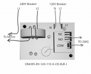
I understand the concept behind the current-sensing relay, but need help both in choosing the correct relay and also in figuring out the wiring. Other posters on this forum have indicated that they've successfully used these relays, but there isn't really a comprehensive "how to" thread, and I'm not quite sophisticated enough to piece it together from the various postings.

So, I am hoping that someone might provide this "how to" advice, given my particular setup below:
--Pentair IntelliFlo Variable Speed Pump (has internal schedule/timer, but clock resets to midnight upon power failure)
--Hayward Aqua Rite (no timer, it's presently hot 24/7, and relies upon the flow sensor to tell it when to send current to the salt cell)
--Pump and SWG are both at 240v and share the same 20A breaker (along with Pentair 400K BTU gas heater).

PS Another solution is adding an Intermatic-type timer to the SWG. However, this is not ideal, because in the event of a power loss, the pump (with its internal timer) and the SWG (using external timer) will not stay synchronized, and so we're back to the potential for the SWG to get power while the pump is off. (In particular, my Pentair VS pump has the common problem that its internal clock resets to midnight if a power failure exceeds a few seconds. Repairing the pump costs nearly as much as replacing the pump, so repair doesn't does not make sense. If the Pentair pump would actually keep accurate time upon power failure , I could simply run the SWG using a digital timer that includes a battery backup.)

Thanks for the help!
 
Last edited:
Until you get your relay implemented you should run your pump 24/7 at an RPM low enough for your SWG to be on.

What is your pump run time and SWG % now?
 
  • Like
Reactions: JT2700
Thanks Allen, from a safety perspective, I agree that the the pump should be running 24/7 until the relay is in place. I am presently not doing that because:
1) I run my pump overnight (8hrs) at reduced electric rates. In my area, daytime summer electric rates are HIGH. And, I need to run at least 1350RPM in order to trip my flow sensor. Below 1350RPM, my flow sensor doesn't trip, and also my pump vibrates pretty badly (not sure if this vibration is normal :confused:).
2) I just installed a brand new OEM flow sensor, so hopefully I won't see another flow sensor failure too soon.......fingers crossed.
3) I'm hoping to get this relay figured out very soon :)
 
What is your cost per KWH during the day time?

I don't think it would cost you more than $25 - $50/ month or maybe $1/day to run your pump 24/7 at 1350 RPM.

Variable_Speed_Pump_Electrical_Costs.jpg
 
During peak hours, I pay approx $0.61/kWh, but that's misleading because "peak" is only 5 hours/day.

Running my pump 8hrs overnight (as I do) costs about $30/month.

I'll spare you the calculations, but running 24/7 @ 1350RPM (including 2 hrs/day at 2100RPM for the pool cleaner), would cost roughly $60/month.

In short, it costs an extra $30/month to punt on the current-sensing relay idea, and instead run the pump 24/7.
 
Last edited:
Sorry, read your post a few days ago but didn't have any time to reply until now. I use a CR Magnetic current sensing relay, part number CR4395-EH-120-110-X-CD-ELR . Here's how I wired mine.
csr.png
I looped one of the motor lines three times through the coil to reduce the sense trip point from 1 to 10 amps down to 0.3 to 3.3 amps. Also, I use 120V to power my SWG. If you want to use 240v to power your SWG, then you will need part number CR4395-EH-240-X-CD-ELR-I. Amazon has them here.. Just connect your L2 where I have my neutral connected. Also, you may want to consider using a separate breaker for the SWG which will allow for shutting off the SWG without shutting off the motor.
I going on my fourth season with it and It works great. I never had to touch it since it was installed.
 

Attachments

  • csr.png
    csr.png
    76 KB · Views: 16
Last edited:
We caution here all the time about relying on just the SWG's flow switch to shut it down when the pump is not running, for the very reason you experienced. But yours is the first incident I've actually read where it happened. Congratulations? ;) Glad you caught it in time.

The current-sensing safeguard seems like a good solution.
 
How are you running your ground wires?
My avatar is a picture of my CSR mounted in a metal electrical box. It's mounted inside of my shed so I didn't have to be worried about a weatherproof enclosure. All the grounds are tied together and grounded to the metal box.
 
Laprjns,

The CSR you used is currently out of stock, so I ordered the below from Grainger.

I *think* it's basically the same device, other than mine has sensing amp range of 2A-20A vs yours at 1A-10A. So, I might have to loop the motor wire an additional time through the coil/loop, in order to get the sensitivity range more appropriate to my pool pump's current draw.

Also, the one I ordered has a "trip on delay" of 0.5-50sec, which theoretically could help avoid tripping the relay on a current spike ("transient"?).


Do you see any issues with what I've ordered?


PS From what I can tell visually, the "Dayton" brand CSR I ordered appears to be Grainger's private-label version of the CSR made by Macromatic, which was (I think) used by someone else on the forum.
 

Enjoying this content?

Support TFP with a donation.

Give Support
I *think* it's basically the same device, other than mine has sensing amp range of 2A-20A vs yours at 1A-10A. So, I might have to loop the motor wire an additional time through the coil/loop, in order to get the sensitivity range more appropriate to my pool pump's current draw.
I think that you need to have as many loops as it takes to get the bottom number of the range (2 to 20 amps) to below 0.5 amps. This would mean at least 4 (.5 to 5 amps). I say this because I believe that you want the power to be turned on to the unit at an rpm below what turns on the SWG flow switch. In my case, my SWG's flow switch activates at 1300 rpm which requires a 0.65 amp draw on my 240V line. The actual current needed by your pump to achieve 1350 rpm may be different but I believe that you will be in the 0.5 to 1 amp range so you will be working at the lower end of the current sense trip point range. The lower you get this range the more room you will have for adjustments. I personally would shoot for six loops.
Also, the one I ordered has a "trip on delay" of 0.5-50sec, which theoretically could help avoid tripping the relay on a current spike ("transient"?).
I didn't even think about a delay when I got my CSR, but if I were to do it again I would most likely get a delay However, this will make getting the trip point range down even more important.
Do you see any issues with what I've ordered?
No, but I assume that there will be a wiring diagram/ instruction sheet included to explain how to configure the white switch in the top left-hand corner (I could find one on the web). I assume that it needs to be switched to the left selecting low to high going current to trip the relay. Also, assume that it will have the pinouts defined for L1, L2, NO, NC, and COM connections.
1653957923751.png
 
Once again, thanks laprjns!

Here is the PDF documentation from the Grainger website: https://www.grainger.com/ec/pdf/6C055_2.pdf

The PDF seems to verify what you said about the # of loops. I just re-checked and my flow sensor is presently remaining in the tripped position at pump RPM of 1400. So, that's a current of 0.73A, very close to your pump's 0.65A threshold.

Also, because I want to the CSR to trip when the pump amps EXCEED a certain value, I think the white switch (upper left corner of the relay) belongs in left "overcurrent" position -- as you also predicted.

My read is that pins 1 & 2 get L1 & L2 from the 240V breaker. And then pins 4 & 5 go to SWG ??

I say this because I believe that you want the power to be turned on to the unit at an rpm below what turns on the SWG flow switch.

I'm a bit confused by your statement above. My thinking: if the SWG gets power from the CSR at a time when pump RPM is below that required to trip to the SWG flow switch, then I'm just powering the SWG for no reason. In other words, no chlorine will be produced under these conditions, so why have the SWG unit powered at all?
 
I'm a bit confused by your statement above. My thinking: if the SWG gets power from the CSR at a time when pump RPM is below that required to trip to the SWG flow switch, then I'm just powering the SWG for no reason. In other words, no chlorine will be produced under these conditions, so why have the SWG unit powered at all?
You are confused because of my poor wording. My CSR is set so that the SWG turns on at around 900 to 1000 rpm. Normally I don't run by pump below 1500 rpm, but there are times like when I want to test the flow switch, I run it below 1300 rpm.
Here is the PDF documentation from the Grainger website: https://www.grainger.com/ec/pdf/6C055_2.pdf
It looks like you will have to connect one of the lines (either L1 or L2) coming from the breaker to pin 3 and make a connection from pin 4 to the motor. The other L will need to pass through directly to the motor.
 
Thread Status
Hello , This thread has been inactive for over 60 days. New postings here are unlikely to be seen or responded to by other members. For better visibility, consider Starting A New Thread.