Is my Hayward pump wired wrong?

IIIpgCIii

Member
May 27, 2021
13
NY
Pool Size
8500
Surface
Vinyl
Chlorine
Liquid Chlorine
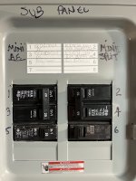
This is year 2 with our pool. The guy I had open the pool, says the pump isn't going as fast as it could, and maybe it was wired wrong. He seems to think it is on 110V but wired for 220v. He says it should prime right away, and be much louder. My breaker is single-pole

All last year, I assumed it was just efficient and quiet.

It is a Hayward SuperPump 700 Series

Attached are images and video.
 
Post a pic of the breaker and also the wiring of any timer you may be using.
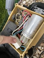
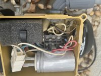
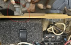
You may want to take the wiring cover off the motor and post a pic of that too.
 
You have a 120v time clock being serviced by a single-pole breaker. Your wiring at the motor is wiring for 120v. You have the 230v connector plug installed at the motor. If your "pool guy" didn't test, with a meter, the voltage at the pump and didn't see the 120v wiring, and the 230v plug, you need a real "pool guy." Its amazing that the motor hasn't burned up running under voltage.
 
You have a 120v time clock being serviced by a single-pole breaker. Your wiring at the motor is wiring for 120v. You have the 230v connector plug installed at the motor. If your "pool guy" didn't test, with a meter, the voltage at the pump and didn't see the 120v wiring, and the 230v plug, you need a real "pool guy." Its amazing that the motor hasn't burned up running under voltage.
Thanks. So if I get the three looped brown wire connector, I should be good?
 
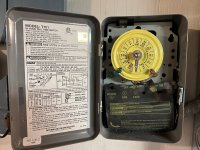
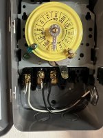
With the CB turned off, remove the plastic cover over the wires in the timer. Take a pic of those wires and post here.
 
Based on the last timer pic and the first one you posted, the timer isn't wired correctly either.
Refer to the wiring diagram in the first timer pic.

There should be two sets of wires coming into the timer box - one from the CB and one from the pump. Either set should consist of 3 wires - 1 black (hot), 1 white (neutral) and 1 green (ground).
Thanks. So I need a new connector for the Super Pump, and I am missing ground wires from the timer?
 

Enjoying this content?

Support TFP with a donation.

Give Support
Is there conduit from the panel where the CB is located all the way to the timer box and is that conduit metal (EMT)?

There should be two separate conduits to the timer box. One from the subpanel and one from the pump.

All I see in your timer wiring pic is 1 white wire and 2 black wires - all coming from one conduit. I also don't see a ground wire. That isn't correct or safe and certainly isn't up to code.
 
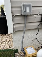
The panel is right next to the timer, in a short "UL" metal conduit. Then romex going from the sub panel to a switch in an outdpoor quadbox at the pump.
 
Thanks. So I need a new connector for the Super Pump, and I am missing ground wires from the timer?
Not necessarily missing wires. It is good to have a ground hooked to the green screw on the timer mechanism. You have the neutral needed to run the clock. The pump neutral is most likely installed to the neutral bus in the panel or the pump would never run at all. The black wire is supplying the power to both the timeclock and (when "on") the pump. You have a ground wire in the pump, so that should be good. Is that timeclock mounted outside? If so it should be a T101R (outdoor box). You have a T101 (indoor box).

What you do appear to be missing, especially as this looks like a new timeclock installation, is a ground-fault circuit breaker installation. This has been a National Electrical Code requirement for over ten years. It requires someone that knows how to wire pool loads (pumps, clocks, etc.) to install correctly.
 
Just to summarize the electrical deficiencies in your pump installation...
  • Pump CB must be GFCI
  • Timer box missing ground on green screw
  • Timer box not outdoor weatherproof model T101R
  • Pump has 240V plug in while wired for 120 volts
Is the pump and your pool properly bonded?
 
Just to summarize the electrical deficiencies in your pump installation...
  • Pump CB must be GFCI
  • Timer box missing ground on green screw
  • Timer box not outdoor weatherproof model T101R
  • Pump has 240V plug in while wired for 120 volts
Is the pump and your pool properly bonded?
The timer is inside.

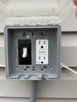
There is no plug on the pump, it is wired directly. The switch on the left controls the pump, so I can turn it off, without going to the basement. the GFCI on the right is what I use to plug the Dolphin robot. pump.jpg

quad.jpg
 
So the CB subpanel and the timer is in the basement?

Does the timer also control the power to the GFCI outlet?

There is a chance that the pump is wired to the LOAD side of the GFCI outlet and is GFCI protected.

Although that GFCI outlet is 15 amps, not 20 amps, and is on a 20 amp breaker if powered fromt he pump CB.
The timer only controls the pump, not the outlets. Both the sub panel and timer are int he basement. The outlets are on a separate breaker.

I have the electrician coming on Thursday to quote me on another project. I will ask him about the GFCI breakers and the grounding of the timer.

I reached out to the pool store where I bought the pump, about a replacement "looped brown connector" that they never gave me.
 
Thread Status
Hello , This thread has been inactive for over 60 days. New postings here are unlikely to be seen or responded to by other members. For better visibility, consider Starting A New Thread.