MasterTemp Trips Breaker / Service light is on

Yes, I just observed this. I think before I was waiting until it said "Service Heater", and then looking into the Fenwal box - at that point the diagnostic Fenwal LED has gone out. If you watch the ignition real time, after the 3rd time lighting, the diagnostic LED inside the Fenwal box flashes 3 times, which according to the diagram on my Fenwal means "Ignition Lockout".

I pulled out my multimeter, put it to VDC, and tested for voltage across the FC+ and FC- pins before, during, and post ignition. It measures 0 VDC, so I believe that I have a flame sensing issue, so the Fenwal is going into Ignition Lockout.

I went down the grounding path as described in the article, and followed the instructions here to add another ground wire, but that has not helped: https://www.pentair.com/content/dam...ire_Kit_Installation_Instructions_English.pdf

Do I replace the Fenwal box, or is there something else I should be looking at? Where is the flame sensing wire? I don't have any signs of corroded wires or critters in my heaters, but I'd still like to trace that down to double check.
 
So I got a brand new replacement Fenwal box - swapped it out, and I'm at the same spot. Heater fires for a second or two, and then turns off. Does this 3x, and then the Fenwal box reports "Ignition lockout". I have already done the grounding suggestion done in https://www.pentair.com/content/dam...ire_Kit_Installation_Instructions_English.pdf, so I'd have to assume that I have a decent ground. As a test, I could pull a ground off of the panel itself - it's about 8' from the heater.

Based off of where I'm at, and it still seems that the heater isn't sensing the flame (I get 0 VDC at the FC+ and FC- pins on the Fenwal), I have a few more questions:
  • What is responsible for flame sensing? Is this built into the ignitor, or something else?
  • What wires coming off of the Fenwal box are responsible for the Flame sensing signal? My wires all "look" good, but I cannot say there's not something behind the insulation that I cannot see...
  • Is there anything else that I'm missing?
 
The logic for the flame sensing and the decision to shutdown the gas valve by stopping 24V to the gas valve is all done by the Fenwal box.

Have you read Heater Flame Sensing - Further Reading


Thanks AJW - yes, I've read the article - multiple times in fact. What I cannot understand from the article is what actually detects the flame? I understand that the Fenwal box is the microprocessor, but since it's detecting 0 VDC across the FC+ and FC- pins., according to the article it leads me to believe that I have a flame sensing issue which could be a bad ground, a bad Fenwal microprocessor, or a bad flame sensing circuit. The Fenwal box was just replaced yesterday, so I have to assume that one of the two Fenwal boxes was good, but the problem hasn't gone away and the flame current sensing pins still read 0 volts. I've already done fix #1:
You can fix these as follows:

  1. Take the blower flange bolts loose and strip a wire with a longish strip ( 1inch or so) then slide it into the gap between the flange and the flame tube, Connect the other end to the yellow ground wires that are ganged inside the control panel (usually next to the Fenwel). Then restart the unit and see if this works. This will ensure you have a good ground connection to the Fenwel which is required to measure the tiny signal. This technique was discovered by Fenwal and is described in their technical documentation on their website.[3] Pentair also sells a kit with the proper parts to perform this modification.[4]

Fix #2 is about rats / rodents. I don't have any visible signs of rodents, but I'd like to understand what actually does the flame sensing so I know what to trace down. The only reference in the article to what actually does flame sensing says that it's "usually one of the wires connected to the igniter". Does this mean that the Ignitor has some component that actually does the flame sensing? If so, I'll order a new Ignitor. I know my ignitor works for the actual ignition portion as the heater does ignite, it just doesn't stay lit, but if it also serves as flame sensing, this would likely be the next logical step as I did the alternate ground as documented by Pentair / Fenwal, and I've also replaced the Fenwal unit, which is processing all of these things.
 
@JamesW Do you know what part is the flame sensor that creates the flame current in the MasterTemp?
 
On a call for heat, the blower and HSI are energized.

In about 20 seconds, the gas valve opens and ignition occurs.

The HSI then switches to a sensing mode and monitors the flame.

Basically, the Fenwal puts out AC voltage to the ignitor and current flows mostly from the ignitor to the burner tray due to the difference in surface area between the ignitor and the burner tray.

This creates a DC current that the Fenwal detects.

The ionized gas in the flame provides the path for the current.

To measure flame current, connect a True RMS or analog DC micro-ammeter to the FC+ and FC- terminals.

Readings should be 1.0 µA DC or higher.

I pulled out my multimeter, put it to VDC, and tested for voltage across the FC+ and FC- pins before, during, and post ignition.
Is it a really good True RMS meter or a cheap meter?
 
On a call for heat, the blower and HSI are energized.

In about 20 seconds, the gas valve opens and ignition occurs.

The HSI then switches to a sensing mode and monitors the flame.

Basically, the Fenwal puts out AC voltage to the ignitor and current flows mostly from the ignitor to the burner tray due to the difference in surface area between the ignitor and the burner tray.

This creates a DC current that the Fenwal detects.

The ionized gas in the flame provides the path for the current.

To measure flame current, connect a True RMS or analog DC micro-ammeter to the FC+ and FC- terminals.

Readings should be 1.0 µA DC or higher.


Is it a really good True RMS meter or a cheap meter?
It's a Craftsmans 82141 that I've had for years. I can't find anything that says "True RMS", so I'm assuming it is not a True RMS meter. It's like this one: https://www.amazon.com/Craftsman-34...d=1&keywords=82141&qid=1632170387&s=hi&sr=1-8

I'll remove a bolt and see if I get water - are you thinking that the manifold isn't opening up or that there's no water flow going through the heater?
 
I'll remove a bolt and see if I get water - are you thinking that the manifold isn't opening up or that there's no water flow going through the heater?

If you get water from the bolt hole when you remove it it is likely the heat exchanger is leaking and the heater is probably beyond an economic repair. The heat exchanger leak could mess us the flame sensing.
 
  • Like
Reactions: JamesW

Enjoying this content?

Support TFP with a donation.

Give Support
If you get water from the bolt hole when you remove it it is likely the heat exchanger is leaking and the heater is probably beyond an economic repair. The heat exchanger leak could mess us the flame sensing.
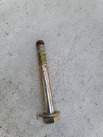
Hey Allen - removed the bottom bolt. No water came out, but the end of the bolt does have corrosion on the tip - not sure if this is normal for a 5 year old heater or not.
20210922_120533.jpg

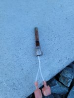
That being said, I slowly started replacing things. I removed the Stack Flu sensor because it was easy to get at. It had corrosion on it, but my exhaust gas temps were still normal. I had a new one on hand, so I replaced it anyway. As you already know, this didn't change things - I still have normal exhaust gas readings, but this may prevent me from having to remove the panels in a few months.
20210922_124710.jpg

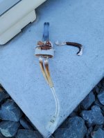
Since the readings are coming from the ignitor, I replaced the ignitor (even though it would light with the old one). My old ignitor looks like it's in tough shape, and the gasket looks even worse. The fiberglass wrap that protects the wires pulled out of the ceramic while I was removing the ignitor - the whole setup looks like it was about due to replace.
20210922_124751.jpg

After replacing the ignitor, the heater would now stay lit - I'm guessing that the corrosion on the ignitor was preventing the small flame sensing signal from getting through, but the larger current for ignition was still working?
 
Sounds like you are good now. Thanks for the update.

I wouldn’t worry about a bit of corrosion on the end of the bolt.

Your igniter is interesting that it will light but not support the flame rectification. Thanks for showing that to us.

Where do you stand with your CB? Is the non-GFCI CB still in? The corrosion on the igniter could have been causing the GFCI trip at times.
 
This is an interesting post. I think my Jandy Jxi has the same igniter but never got the rust colored deposits or what looks like cracks in the insulator after years of heavy use. The cracks could have also been part of the problem if they provided another path to ground through the firebox where the insulator is inserted. Looks like we now have another thing to check on the igniter that's not documented anywhere else to my knowledge. Thanks very much for this follow up information. I bet it may help others in the future.

Chris
 
Sounds like you are good now. Thanks for the update.

I wouldn’t worry about a bit of corrosion on the end of the bolt.

Your igniter is interesting that it will light but not support the flame rectification. Thanks for showing that to us.

Where do you stand with your CB? Is the non-GFCI CB still in? The corrosion on the igniter could have been causing the GFCI trip at times.
I still have the non-GFCI CB installed, and it hasn't tripped - so it's inconclusive at the moment if the ignitor was causing the GFCI trip or not - I'll have to swap back to see if it trips. Right now I'm at a better spot than I was last week - so thank you for that. (y)
 
The flame current is in the microamp range, so corrosion on the ignitor/flame sensor can cause enough resistance to prevent the current.

A leaking stray current can interfere with the flame current signal.

If the gfci is tripping, then you might have a voltage/current leak sending voltage into the heater chassis/frame and grounding wires.
 
As James points out the flame sense is incredibly sensitive. I found this out the hard way with a lot of help from him and others. I had a major lightning strike that exploded an expensive palm right next to the house and fried my security system and other things. My pool heater required a lot of replacements and there was no question boards were burnt up. But I still couldn't get it to run without a flame sense error. I spent weeks trying everything including carefully bypassing each safety sensor one-at-a-time and even trying to simulate flame sense circuit on the heater with home-made equipment running in parallel with the igniter circuit. The current measured on the Fenwal was never right so something was interfering. As a last ditch effort I ran a temporary power line to the unit and voila, it worked! As it turns out the lightning strike had cause a bunch of tiny holes in the insulation of one of the conductors in the power supply wire. This allowed a tiny leakage of current to the bare ground wire that was right next to it in the conduit. It was not enough to even trip the GFI but it certainly played havoc with the flame sense circuit. I replaced the wires and it has worked without even a blip ever since.

You haven't had any lightning lately, have you?

Chris
 
  • Like
Reactions: JamesW
Thread Status
Hello , This thread has been inactive for over 60 days. New postings here are unlikely to be seen or responded to by other members. For better visibility, consider Starting A New Thread.