
Howdy,
I have a Pentair MASTERTEMP 400 natural gas heater, manufactured 8/15/2016, model# 460736 (standard model, not the HD/ASME). I just replaced the thermal regulator (original was corroded shut). I've been troubleshooting, the heater currently has the following issues:
1) Automatic Gas Shutoff Switch (AGS) is bad (measures open circuit when cold). I temporarily bypassed this bad switch for further testing.
2) Control Board is bad (I went through the "Heater Will Not Fire - C" troubleshooting chart in the manual, and determined that there is no 24 VAC between the GAS terminals on the Control Board (about 24 seconds after call for heat). I get 4.9 to 5.3 VAC open-circuit (when not plugged into gas valve TR/TH terminals, measured at Control Board connector), when plugged in (loaded) I get 0 VAC. So the 24 VAC drive circuit for the GAS terminals on the Control Board must be shot.
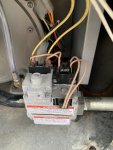
3) The Combination Gas Control Valve is not opening to flow gas when manually actuated (heater does not light, no gas smell, gas meter does not move). The valve is normally actuated (Control Board) by ~ 24VAC. I manually applied 26VAC using a sprinkler timer wall transformer, to mimic the timing/duration of the voltage from the Control Board. I disconnected the pink/orange wires from the TR/TH terminal block terminals (see photo) and applied the 26VAC there, so I know the wiring and ON/OFF switch is good because I can hear the gas valve actuator clicking on/off.
Question: Is there any other troubleshooting I can do on the Combination Gas Control Valve? As stated, the (electromagnetic?) actuator seems to be working (a very audible click on/off with applied 26VAC). Could there still be something wrong with the actuator? What else could cause the gas valve not to flow? Is there a screen in the valve that could be clogged? Can these Combination Gas Control Valves be rebuilt? Or if bad would I need to buy a whole new unit?
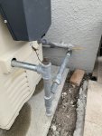
Please see second pic. The gas ball valve (yellow handle) was open for these tests. I removed the bronze cap (for future gas grill hookup) and confirmed there is plenty of gas available/flowing and saw the gas meter turning when line open.
I hate to have to replace this heater already since it's only 4 years old! If the gas valve worked, I was willing to spend the money on a new Control Board ($$$) and AGS switch ($) to get it back up and running. But if the gas valve is bad also ($$), I think it's time to look into a new replacement heater!
Any suggestions on my questions above would be much appreciated! Thanks!
I have a Pentair MASTERTEMP 400 natural gas heater, manufactured 8/15/2016, model# 460736 (standard model, not the HD/ASME). I just replaced the thermal regulator (original was corroded shut). I've been troubleshooting, the heater currently has the following issues:
1) Automatic Gas Shutoff Switch (AGS) is bad (measures open circuit when cold). I temporarily bypassed this bad switch for further testing.
2) Control Board is bad (I went through the "Heater Will Not Fire - C" troubleshooting chart in the manual, and determined that there is no 24 VAC between the GAS terminals on the Control Board (about 24 seconds after call for heat). I get 4.9 to 5.3 VAC open-circuit (when not plugged into gas valve TR/TH terminals, measured at Control Board connector), when plugged in (loaded) I get 0 VAC. So the 24 VAC drive circuit for the GAS terminals on the Control Board must be shot.
3) The Combination Gas Control Valve is not opening to flow gas when manually actuated (heater does not light, no gas smell, gas meter does not move). The valve is normally actuated (Control Board) by ~ 24VAC. I manually applied 26VAC using a sprinkler timer wall transformer, to mimic the timing/duration of the voltage from the Control Board. I disconnected the pink/orange wires from the TR/TH terminal block terminals (see photo) and applied the 26VAC there, so I know the wiring and ON/OFF switch is good because I can hear the gas valve actuator clicking on/off.
Question: Is there any other troubleshooting I can do on the Combination Gas Control Valve? As stated, the (electromagnetic?) actuator seems to be working (a very audible click on/off with applied 26VAC). Could there still be something wrong with the actuator? What else could cause the gas valve not to flow? Is there a screen in the valve that could be clogged? Can these Combination Gas Control Valves be rebuilt? Or if bad would I need to buy a whole new unit?
Please see second pic. The gas ball valve (yellow handle) was open for these tests. I removed the bronze cap (for future gas grill hookup) and confirmed there is plenty of gas available/flowing and saw the gas meter turning when line open.
I hate to have to replace this heater already since it's only 4 years old! If the gas valve worked, I was willing to spend the money on a new Control Board ($$$) and AGS switch ($) to get it back up and running. But if the gas valve is bad also ($$), I think it's time to look into a new replacement heater!
Any suggestions on my questions above would be much appreciated! Thanks!
Attachments
Last edited: