Intellitouch i9+3 problem after storm

J,

Excellent!!! The heater is normally controlled by a small relay on one of the boards... It basically interrupts the path for 24 volts AC from the heater and then back to the heater. The Circuit is called the Firemans switch.. When the relay is open the heater does not work, and when the relay is closed the heater turn on. The heater is normally set to full hot and the automation monitors the water temp probe. If the water is less than the set point that you enter into the automation, the relay closes and turn the heater on. When the water temp gets up to the set point, the relay opens and the heater stops.. You should be able to just remove the two wires going to the heater connection and short them together and see if the heater fires up.. If you have a meter, you can then test the relay to see if you have continuity or not.

The heater connection is the two pin connector with the black and white wires at the top left of your picture..

Glad you got it working, almost...

Jim R.

Okay I know the wires you're talking about. I'll try to short them in the morning and see what happens. If that works I can use my mulimeter to check for continuity.

Thanks again, Jeff
 
Nice, I'm glad it's getting close and that i didn't cause you to go buy new boards!!

If Jim's heater suggestion works then we need to check whether the relay driver is working (one of the 3 the unl2803 chips)... I mapped out which chip runs the k5 relay but it's at home and I am not back to Monday.
 
So this morning I've done some testing.

First I disconnected the black and white wires from the pool heater relay and tried the short them. Heater didn't fire. Found out that if either the white or black wire is disconnected the heater panel looses power. This must be a safety mechanism for loose wires or something.

Next I inserted both the black and wires into one of the relay terminals to short it out. The heater didn't fire ( but there was power to the control panel ) so I'm uncertain that it's as simple as if the circuit is complete or shorted the heater automatically fires???

I did make sure the pump was running to provide enough flow to not disable the heater.

I then hooked everything back up and used my multimeter to check continuity.

I first placed probes on the copper wires going into the terminals. There is continuity. I then removed the black relay terminal plug (1st image ) and used the 2 pins to check continuity and everything checked out. I'm not an electrical guru but I assume this means the relay circuit is intact.

One question I have is should the relay circuit always remain in continuity even if powered off. I tested both with the heater light on the front panel on and off in service mode. Also in auto mode with the heater turned on and off in both the pool and spa section with the temp set above the set point ( this also turned the heater light on, on the panel). The relay was always in continuity touching the two pins.

I still don't know if this proves that the relay is functioning or not. Not sure how I can check that. I'm not super knowledgeable in electronics diagnostics.


20190512_105538.jpg20190512_105526.jpg
 
Jeff,

You do not want to be measuring ohms (continuity) with heater on, as there will be 24 volts AC on the black and white wires..

Try this.. With the black and white wires connected to the circuit board and the heater on (as in powered up and the pump running) set your meter to read volts AC and measure between the two silver connector screws.. With the automation set to NO Heat, you should see 24 VAC between the two pins.. When you turn the set point up to turn the heater on, the voltage will go to zero volts.. The is because with the relay open (No heat) you will be measure the 24 VAC from the heater.. When the relay is closed (Heat needed) the voltage is provided to the heater to let it turn on.. (Not exactly technically accurate, but close enough for this forum..)

Thanks,

Jim R.
 
Okay thanks for the clarification. I tried the below with the heater powered on and the pump running (both with the heater fired up and heating via manual setting and with the heater powered on but not heating).

With automation set to no heat no voltage is measured across the two screws.
With the set point turned up no voltage is measured across the two screws.
 
Jeff,

That would indicate that the relay is always closed.. Not sure that is true or if we just have a test issue...

So try this.. Disconnect the connector with the black and white wires.. Then using an ohm meter test for continuity between the two pins on the board with the automation off. You should get an open.. If you get a continuity, it means the relay is stuck in the closed position..

If you get an open.. then power up your automation and set it to call for heat.. You do not need the heater running to do this test, as the control to the heater is disconnected. In theory, the relay should close when the automation calls for heat.

Thanks,

Jim R.
 
Ran the test and it looks like it's stuck in closed. Get continuity with automation off.

So the million dollar (or at least a couple grand) question is do I have a bad relay or is the mobo bad and not able to send commands to the personality board to change the state of the relay?

Another question. If the relay was is stuck in the closed position shouldn't it be keeping the heater on at all times rather than off. I will say the day after the storm we noticed the pool warmed to 100 degrees on it's own and I couldn't turn it off remotely. I though it was just the protocol adapter and I had manually turn it down. Maybe that's when the relay got stuck in closed state.
 
Jeff,

With the power off, there should be no way for the relay to remain closed unless it is stuck..

You could tap on the relay.. Tom believes it is K5... If it becomes unstuck you will know it is the relay for sure...

You might want to PM Tom (ogdento) and see what options he might have for you...

@ogdento

Thanks,

Jim R.
 
Also further confirmation that the relay is stuck or not functioning. From my earlier photos you can see adjacent relays (same part number as the heater relay) controlling the valve actuators. When I activate those via the app I hear the familiar click. I hear no click when I turn the heater on or off.

I found this part from amazon:

Amazon.com : Pentair RLYHTR Heater Relay Repair Replacement Kit ComPool Pool and Spa Automation Control System : Outdoor Spas : Garden & Outdoor

In this catalog it's listed as a replacement part for intellitouch automation. See here: https://www.pentairpartners.com/productcatalog/pdf/US2018/sec16_RP_Automation.pdf

I went ahead and ordered it just to see if its the relay. Can return it if not and will also give me some diagnostic info. If it doesn't work it may be the board or controller chip as Tom suggested.
 

Enjoying this content?

Support TFP with a donation.

Give Support
Jeff,

If the relay would not close, it could be the board or the relay driver chips.. but, since the relay is closed even when no power is applied to the system, the only thing that it can be is a bad relay.

Do you have any experience soldering or unsoldering components from a circuit card?

Jim R.

A little bit from a long time ago but not where I'd want to mess with it yet. The picture of the part I ordered looks to be plug and play. Like it connects to the pins and bypasses the relay on the board. I would guess since this is a pretty critical relay to fail on an automation system they had to put a part that would allow a relatively easy repair without having to spend the money to replace the board. Lots of unhappy customers. The part is still a rip off for what it is but cheaper than a new board. I'll let you know if this is what it appears to be.
 
Last edited by a moderator:
Have no clue :). Will have to get the part, inspect it and go from there. My though it it connects to the pins on the board and then the two green wires could connect to the white and black wires via wire nuts. Problem is on the picture the connector looks too small to fit on the pins.

I'll just have to wait and see if I can make sense of it. I also sent a message to pentair today to ask if this could replace the relay. I hope they reply.
 
Sorry for the late reply, I was at the US Women's Soccer Team match today...

Yikes a bad relay!! That's not great for my statement that personality boards don't fail often! ?

Actually the only one I've seen fail was reportedly dropped, breaking one of the relays!

Jim I'll send you a quick note
 
Jeff,

Since the old relay is shorted you can't connect to its pins.. And those relays are soldered in place..

I looked at the pic of the relay kit that you bought and it appears to me it is designed to plug into the Electric heater output.. Which would work just fine, except for one thing.. You already have something plugged into that connector right now??? It is in your post 23 pic on the top left.. Elec Htr

Any idea what is plugged into it now???

Jim R.


Ahh good point about the pins. The electric heater port is currently wired to an free relay on the power station so I could just unplug it and use that port if that would work. I didn't know if the computer activates that port as well when receiving heater commands.
 
Jeff,

I am pretty sure that both the gas heater and electric heaters circuits come on at the same time.. So, just unplug what is there now and plug in the kit you have coming.. The green wires on the kit get connected to the two wires coming from your heater...

You might want to test it first before connecting it to the heater wires... no heat means there should be no continuity between the green wires.. with heat there should be continuity.. The heater does not need to be running to test.

Thanks,

Jim R.
 
Hey guys,
This may be a moot point by now - but here's some data on the relays, and what I've got for pinouts for the 2803 relay driver chips on the personality board...

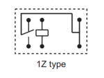
The board I'm looking at has HFD23 024-1ZS SPDT (single pole, double throw), 24 volt DC relays. The Omron G5V-1 is pin-for pin compatible and is used on another personality board I've got. If you look at the schematic, you'll see there is a normally closed contact, so those pins are going to be closed with no power applied to the coil.
101045

Pin 14 on U13 is what drives K5 and the relay that would plug into the Electric heater (ELECT HTR) connector. You could set your meter to DC volts and see if you get 24 at the ELEC HTR connector when the heat is on.

This is what I've got for pinouts of the 2803 driver chips (I only traced the output side):
U13
10 11 12 13 14 15 16 17 18
com 2spd solr k5/ A8
elht
U12
10 11 12 13 14 15 16 17 18
com A7 A6 A5 A4 A3 A2 A1 FP

U11
10 11 12 13 14 15 16 17 18
com spa xp3 xp2 xp1


-Tom
 

Enjoying this content?

Support TFP with a donation.

Give Support
Thread Status
Hello , This thread has been inactive for over 60 days. New postings here are unlikely to be seen or responded to by other members. For better visibility, consider Starting A New Thread.