SWCG, Automation, and Electrical Setup

Cdubcincy

Member
Jun 8, 2020
18
Frisco, Texas
Pool Size
13000
Surface
Plaster
Chlorine
Salt Water Generator
SWG Type
Hayward Aqua Rite (T-9)
Hello TFP! I've been a lurker here for over a year since I bought a house that had a pool and it has been an immense help in getting my water chemistry under control(CYA was off the charts on the first test!). Now that I have a full summer under my belt with good results I've been looking at how to optimize my SWCG and pool/spa for the winter. Details on my setup:

- 12,500 inground gunnite pool/spa
- Spa plumbed for spill-over and solo flow
- Hayward Ecommand4 panel
- Aquarite AQR9 SWCG
- Hayward heater
- Booster pump
- Blower for spa

The issue I'm trying to resolve is that the SWCG is wired in with the filter and the only control on generation is by adjusting the dial on the panel. This is fine during the summer but as things cool down my kids tend to use our spa as the "pool" for the winter which leads to it being on quite often at a higher than needed generation rate. I took a look at the AQR9 manual and it clearly shows how to wire the SWCG to the Ecommand4 which would allow for the pool and spa to operate at different generation percentages. I went out and bought the correct 4 conductor cable and when I took the front off the Ecommand4 was a little concerned with what I found.

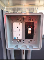
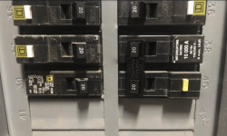
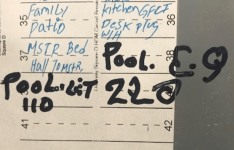
Starting with the basics, below are pictures of my main panel in my house. Breaker 39 is the 110v for the pool and 38/40 are the 220v for the pool. The first thing that jumped out at me was the 110 is not a gfci breaker, but when I followed it out to the pool pad I noticed that the outlet below the panel does have a gfci receptacle.
1633356704472.png
1633356766182.png
1633356871787.png

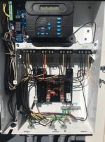
Now is where it really got interesting, the Ecommand4 subpanel does not have any breakers installed and the line voltage coming in and the loads going out are all wired directly to the controlled relays. Looking a little further at the Filter Pump load out wiring shows that one set of the wiring actually goes out to the Filter Pump but the other set of load outs goes to a wire nut that is also powering the SWCG and the Heater.
1633356963467.png

So this leaves me with a few questions:

1. First for sake of safety is the 110v ok with it being wired through the gfci receptacle below the panel and not on a gfci breaker at the main house panel or a gfci breaker inside the Ecommand 4 subpanel?
2. How common is this style of wiring where they completely bypassed the local subpanel and everything is wired directly into the relays? If nothing else it would seem to be more convenient to have local breakers for each piece of equipment to identify issues.
3. Is there an easy way to implement my intended control scheme with the Ecommand4 handling the SWCG generation percentage based on pool/spa mode? In the manual it shows that the SWCG must be wired to the incoming 220v so that it is "always on" and then the automation sends the run signal and percentage values. In order to achieve this setup it would seem that I need switch the setup to have incoming voltage landed at the subpanel and then add 2 breakers, 1 to supply power to the filter pump relay and the 2nd to supply power to the SWCG.

Thanks in advance for any advice in this area and sorry for the lengthy and details post.

Thanks,
Cory
 
1. First for sake of safety is the 110v ok with it being wired through the gfci receptacle below the panel and not on a gfci breaker at the main house panel or a gfci breaker inside the Ecommand 4 subpanel?

That is fine. A GFCI receptacle is an alternative to a GFCI breaker.

2. How common is this style of wiring where they completely bypassed the local subpanel and everything is wired directly into the relays? If nothing else it would seem to be more convenient to have local breakers for each piece of equipment to identify issues.

It looks like the eCommand automation was retro-fitted to the pool sometime after the pool electrical was installed.

When the automation is installed as part of a new build the Load Center doubles as the lectrical subpoenable.

3. Is there an easy way to implement my intended control scheme with the Ecommand4 handling the SWCG generation percentage based on pool/spa mode? In the manual it shows that the SWCG must be wired to the incoming 220v so that it is "always on" and then the automation sends the run signal and percentage values. In order to achieve this setup it would seem that I need switch the setup to have incoming voltage landed at the subpanel and then add 2 breakers, 1 to supply power to the filter pump relay and the 2nd to supply power to the SWCG.

No need to add CB's unless you want to do the work.

Disconnect the SWG power from the wire nuts and pickoff power from the LINE side if the filter/pump relay. That keeps the SWG on the existing CB.

It looks like there is more then one wire under the LINE screws on the relay so something else is picking off power from the LINE side. Your pic is too small for me to see clearly what is going on with your wiring.
 
ajw22 - Thanks for the quick reply!

It looks like there is more then one wire under the LINE screws on the relay so something else is picking off power from the LINE side. Your pic is too small for me to see clearly what is going on with your wiring.

You are correct, the Filter Pump line in is jumped over to Aux 1(Blower) which is then jumped over to Aux 2(Cleaner Pump). Based on your reply it would seem that I could connect the SWCG at Aux2 line in where it only has 1 set of wires landed?
 
ajw22 - Thanks for the quick reply!


You are correct, the Filter Pump line in is jumped over to Aux 1(Blower) which is then jumped over to Aux 2(Cleaner Pump).

So you have the pump, booster pump, blower, heater, SWG all on one 20 amp 240V CB.

How many amps is listed on the pump and booster pump motor data plates?

According to NEC CBs shall not be loaded at more than 80% of rated capacity. That is 16 amps for a 20 amp breaker.

Based on your reply it would seem that I could connect the SWCG at Aux2 line in where it only has 1 set of wires landed?

That sounds like it would work.
 
So you have the pump, booster pump, blower, heater, SWG all on one 20 amp 240V CB.

How many amps is listed on the pump and booster pump motor data plates?

According to NEC CBs shall not be loaded at more than 80% of rated capacity. That is 16 amps for a 20 amp breaker.
Yes, that is how it is currently wired. Max amps for pump is 10.5, cleaner pump is 6.9, blower is 4.5 amps, and the SWCG I usually see pulling about 4.5 amps. Based on the above it would seem that I need an electrician to come out and swap the 2 pole 20 amp breaker out for a ~40amp.
 
Based on the above it would seem that I need an electrician to come out and swap the 2 pole 20 amp breaker out for a ~40amp.

Not that simple.

The wire between the breaker and the eCommand is probably 12 gauge.

For a 40 amp breaker you need 8 gauge wire pulled.

If you do that then run 40 amps or 60 amps into the eCommand load center and reqire the ecommand with individual breakers.
 
  • Like
Reactions: Mdragger88
For a 40 amp breaker you need 8 gauge wire pulled.

If you do that then run 40 amps or 60 amps into the eCommand load center and reqire the ecommand with individual breakers.
The main feed is definitely 12 gauge wire so that will need to be repulled. Would you keep the (1) gfci in the main panel in the house and then use standard breakers in the subpanel?

For the subpanel breakers I'm thinking it would be:
1 x 20 amp for the pump(10.5 amps) and blower(4.5 amps)
1 x 20 amp for the heater(5.5 amps), cleaner(6.9 amps), and swcg(1.0 amps)
 
Main panel breaker should be regular CB.

20A 240V GFCI main pump + SWG. You want SWG to lose power if pump goes off.
20A 240V GFCI for booster pump and blower. You never use those at the same time anyway
20A 240V GFCI for heater. Although heater can be rewired for 120V and use a 120V CB.

If you get a CB GFCI trip it lets you isolate which devices are causing the trip.

Have the electrician run a neutral to the panel so you can also have 120V in the eCommand for the future. So you should have 2 hots + neutral + ground run from main electricasl panel to eCommans subpanel.
 
20A 240V GFCI main pump + SWG. You want SWG to lose power if pump goes off.
For this I would have both hooked up to the line in side correct? With my new configuration I want the SWCG to always have power so the Ecommand4 can change the output % if it’s in spa mode.
 
For this I would have both hooked up to the line in side correct? With my new configuration I want the SWCG to always have power so the Ecommand4 can change the output % if it’s in spa mode.

Yes, you are just using the relay connection as a terminal block.

What type of main pump do you have? VS pump? SS pump?
 

Enjoying this content?

Support TFP with a donation.

Give Support
First for sake of safety is the 110v ok with it being wired through the gfci receptacle below the panel and not on a gfci breaker at the main house panel or a gfci breaker inside the Ecommand 4 subpanel?
It'd be worth a peek into that 110v GFCI & switch box to make sure that everything is "downstream" and protected by the GFCI when it trips.

Based on the above it would seem that I need an electrician to come out and swap the 2 pole 20 amp breaker out for a ~40amp.
This is how my pool is wired. It seems like this would be the "correct-est" but also possibly more expensive solution. How many spaces does your main panel have? Any other room for expansion? If those are the only open spots on your panel, your electrician will have to swap the 110 breaker over to the other side and use your last 2 open slots for a 220 20a GFCI for the blower. Not ideal. In both scenarios, sparky is gonna have to pull wire from your main panel to the pool pad, it's just a question of whether they pull 40A 220v kind of wire or another 20A 220v kind of wire. Copper is expensive, yes, but it's the labor that'll be the big part of the quote I suspect.

My pool panel doesn't have that load center built in, so I have a 40A 220 breaker feeding a subpanel out at the pool equipment. Same 8 blades as you have, just a separate panel box.


Wires from the CB and the SWG go to LINE screws.

Wires from Tristar pump goes to LOAD screws.

If CB trips pump and SWG shuts down.
I'm not an expert but want to double check this. Mine is wired up backwards from this, but that's also because I have a VS pump that stays powered all the time and the panel controls RPMs. It might also have something to do with the style of SWG and power supply I have? AquaRite manual seems to confirm this as well: It's my understanding the SWG needs to be on the LOAD, not the LINE side of the filter pump relay. This way it's protected by both GFCI breaker AND the pool equipment turns off the relay when filter pump is "off". The panel brains take care of the SWG cell cycling via low voltage communication wire.

If the SWG is wired to the LINE lugs, it will get power even when the pump relay is switched off and could be dangerous if the SWG energizes with no water flow.


EDIT: removed photos
 
Last edited:
This is how my pool is wired. It seems like this would be the "correct-est" but also possibly more expensive solution. How many spaces does your main panel have? Any other room for expansion? If those are the only open spots on your panel, your electrician will have to swap the 110 breaker over to the other side and use your last 2 open slots for a 220 20a GFCI for the blower. Not ideal. In both scenarios, sparky is gonna have to pull wire from your main panel to the pool pad, it's just a question of whether they pull 40A 220v kind of wire or another 20A 220v kind of wire. Copper is expensive, yes, but it's the labor that'll be the big part of the quote I suspect.

My pool panel doesn't have that load center built in, so I have a 40A 220 breaker feeding a subpanel out at the pool equipment. Same 8 blades as you have, just a separate panel box.

You have a very different situation then the OP.

He will not be adding any breakers to his main panel. The slot where the 20Amp pump breaker is will be used for the the 40A breaker feeding his new subpanel.


If the SWG is wired to the LINE lugs, it will get power even when the pump relay is switched off and could be dangerous if the SWG energizes with no water flow.

His SWG power on and off will be controlled by a RS-485 data line he intends to install as described in post #1. That will be the primary safety switch with the flow switch being the secondary safety switch.
 
Thanks for reminding me to re-read the thread. I see now that OP is considering a new homerun for 40A service, which I believe is the "correct-est" solution. They even might be able to get the electrician to reuse the original 20a GFCI 220v breaker, saving a few bucks.

You have a very different situation then the OP.
I'm here to learn and felt like I acknowledged this adequately. Cosmetically our setups are very different. The blades for his outside circuit breakers are inside his pool panel, mine are above it in a separate box. The only real difference between our two setups is I have a dedicated 220v 20A GFCI breaker for the blower, a VS pump, and I have one more GFCI for troubleshooting equipment issues. Very different? Maybe. The electrons don't care what wire or box they run through and the only thing that matters is fire and electrocution safety and what OP chooses is the correct method for their situation.

I don't want to get too far into the weeds on this, but it seems like my confusion on this issue and where you and I might have a personal disagreement is which side of the pump relay switch the wire to the SWG power supply goes. I'm hearing you say the control cable and flow switch are two safety factors that are enough, and that's fine if that's your personal threshold for safety. The third safety factor that I'm suggesting is perhaps a personal option that OP might want to consider, and is definitely recommended by the manufacturer and a number of users on this site. It almost sounds like you recommended the same in post #8:
You want SWG to lose power if pump goes off.

I 100% agree and I'm approaching this same principle from a slightly different perspective. I'm not aware of any benefit to leaving any SWG electronics powered on if the pump isn't able to move water past it. I am aware that there is a very small risk of the SWG creating chlorine if there isn't adequate flow, which can in rare circumstances cause an explosion. Low voltage relays, flow switches, microprocessors all can and do fail. Especially if it's on a physical relay switch with a single speed pump, that adds a level of safety that I personally prefer. If the relay fails open, the pump and SWG can't work and will be easy to troubleshoot. If the relay fails closed, the pump and SWG will stay on 24/7 and the panel will take care of the SWG cycle time. Everyone has a different threshold of safety, and I appreciate the opportunity to respectfully discuss and learn.

 
I 100% agree and I'm approaching this same principle from a slightly different perspective. I'm not aware of any benefit to leaving any SWG electronics powered on if the pump isn't able to move water past it. I am aware that there is a very small risk of the SWG creating chlorine if there isn't adequate flow, which can in rare circumstances cause an explosion. Low voltage relays, flow switches, microprocessors all can and do fail. Especially if it's on a physical relay switch with a single speed pump, that adds a level of safety that I personally prefer. If the relay fails open, the pump and SWG can't work and will be easy to troubleshoot. If the relay fails closed, the pump and SWG will stay on 24/7 and the panel will take care of the SWG cycle time. Everyone has a different threshold of safety, and I appreciate the opportunity to respectfully discuss and learn.
This is definitely something I am confused about from the Hayward directions. I understand the standard install methodology of only needing to have power when the pump is running. When I switch it over to the Ecommand4 controlling the SWCG output it clearly says to switch the power over to the "always on" configuration. I'm not sure what benefit the SWCG gets from now always having power when it used to work fine with getting power only during pump run hours.
 
When I switch it over to the Ecommand4 controlling the SWCG output it clearly says to switch the power over to the "always on" configuration. I'm not sure what benefit the SWCG gets from now always having power when it used to work fine with getting power only during pump run hours.
That's interesting. I'm sure someone here has experienced this, or you may be able to get more info from Hayward customer support? It might have something to do with their software needing regular communication from the SWG control unit in order to have their system not kicking off errors because it's constantly pinging a piece of gear that's powered off.
I'm not sure what benefit the SWCG gets from now always having power when it used to work fine with getting power only during pump run hours.
That's fascinating! Usually troubleshooting stuff like that I'd go look at what changed... firmware update? New control software? new hardware installed?
 
That's fascinating! Usually troubleshooting stuff like that I'd go look at what changed... firmware update? New control software? new hardware installed?
The only change is that I'm switching from manual control to Ecommand4 control of the SWCG. I was more saying that it worked fine as it was first wired, now that I'm switching the above it also has me switching the power wiring.
 
I 100% agree and I'm approaching this same principle from a slightly different perspective. I'm not aware of any benefit to leaving any SWG electronics powered on if the pump isn't able to move water past it. I am aware that there is a very small risk of the SWG creating chlorine if there isn't adequate flow, which can in rare circumstances cause an explosion. Low voltage relays, flow switches, microprocessors all can and do fail. Especially if it's on a physical relay switch with a single speed pump, that adds a level of safety that I personally prefer. If the relay fails open, the pump and SWG can't work and will be easy to troubleshoot. If the relay fails closed, the pump and SWG will stay on 24/7 and the panel will take care of the SWG cycle time. Everyone has a different threshold of safety, and I appreciate the opportunity to respectfully discuss and learn.

In post #1 the OP says "In the manual it shows that the SWCG must be wired to the incoming 220v so that it is "always on" and then the automation sends the run signal and percentage values."

I did not feel the need to fact check that in whatever manual. Feel free to do so.

Controlling the SWG power using RS-485 is becoming a common technique among manufactures. Pentair is now doing it in the IntelliConnect and has changed the recommendations for SWG power hookup.

The automation cannot make changes to the SWG programming if its power is off because the pump power is off.
 

Enjoying this content?

Support TFP with a donation.

Give Support
Thread Status
Hello , This thread has been inactive for over 60 days. New postings here are unlikely to be seen or responded to by other members. For better visibility, consider Starting A New Thread.