Need Help with Intellibrite Lights and Pentair Easy Touch 4

Aug 30, 2020
11
Las Vegas
Hello,

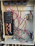
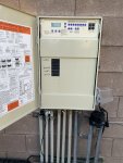
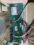
We just had our Hayward PoolBoss replaced with an EasyTouch 4 system. Our pool and spa lights had also stopped working and we thought we needed new bulbs. Turns out we needed a whole new light. The old lights were Fiberstar color changing lights with a color wheel inside. The new lights are Intellibrite 5G 120 V Color changing lights. The guy that installed them left and afterward I noticed that the pool lights were left on. I went outside to turn them off, they won't turn off. The only way I got them turned off was to flip the breaker. I called the company to come back but he hasn't yet and honestly I don't have a lot of faith that he will know what he did incorrectly. Can someone explain how these lights should be wired inside the EasyTouch system? The lights have a breaker inside the box that also powers a GFCI outlet on the outside of the box. Thanks in advance for any info!
 
Frustrated,

The pool lights have to be controlled by one of the 3 Aux relays.. Aux 1, 2 or 3.

I suspect that the installer added a label on each button on the main panel. Just push the button to turn it on and off. Worst case it will shut itself after the circuit egg-timer runs out.. The default is 12 hours but you can set it to what you want.

I have an appointment in a few minutes, but let me know if you found the button on the main panel.

Do you have ScreenLogic??? Or do you have a Pentair remote?

I'll look back in after my appointment..

Thanks,


Jim R.
 
Hi Jim, Thanks so much for your reply. There is a button for the lights but pushing it does nothing.. lights stay on. I do also have ScreenLogic and toggling lights on and off there doesn’t do anything either. The only thing that worked was shutting off the breaker. Any other ideas? I’m usually really good at following instruction manuals or things I find online but nothing I find in the manual for the easy touch or the light is helpful. Thanks again for your time!
 
F,

Show me a couple of pics of your EasyTouch so that I can see the relays and circuit breakers.. Also show me a pic of all the buttons.

It sounds like it is mis-wired to me..

Thanks,

Jim R.
 
F,

Show me a couple of pics of your EasyTouch so that I can see the relays and circuit breakers.. Also show me a pic of all the buttons.

It sounds like it is mis-wired to me..

Thanks,

Jim R.
Thanks Jim, that is what I think as well but I’m not sure which part is wrong. pictures attached.
 

Attachments

  • 62D9F13E-4C67-44A0-AFAE-8B8B12CA703C.jpeg
    62D9F13E-4C67-44A0-AFAE-8B8B12CA703C.jpeg
    520.9 KB · Views: 45
  • A1222E57-2A83-4D92-B5F1-8AA90A0FF77B.jpeg
    A1222E57-2A83-4D92-B5F1-8AA90A0FF77B.jpeg
    656.5 KB · Views: 40
  • 32D41994-2F37-457D-8B5C-15130EA6A821.jpeg
    32D41994-2F37-457D-8B5C-15130EA6A821.jpeg
    479.5 KB · Views: 39
F,

The installer did not use the Aux 2 relay to control the light.. It is obviously wrong, but I am trying to figure out what he did.. It is odd.

Let me see what I can work out..

Thanks,

Jim R.
 
F,

The installer just wired the light straight from the GFCI to the lights.. You need to interrupt the path and insert the Aux 2 relay contacts to control both lights..

1. Remove the black wire between the light breaker and the Line side of Aux 2.. Throw it way..

2. Remove the red and black wires from the bottom back GFCI connection. They now go straight to the lights, you need to connect those two wires to the LOAD side of the Aux 2 relay. (Will have to use wire nuts and a jumper wire.

3. Run a wire from the now empty (bottom back) connection on the GFCI outlet to the LINE side of the Aux 2 relay..

After the fix, GFCI power will go from the outlet to the Aux 2 relay and stop.. When the relay is turned on, power will pass through the relay and then to the lights.

What kind of pump do you have??? Single speed or VS???

Thanks,

Jim R.
 
Like this, and it will be Aux 2 on the ET panel.
I suspect Ground (green)is also not wired correctly, please take a better picture and unwind the green wires to see where they go.
It seams the socket also does not have ground correctly.
 
Last edited:
Like this, and it will be Aux 2 on the ET panel.
I suspect Ground (green)is also not wired correctly, please take a better picture and unwind the green wires to see where they go.
It seams the socket also does not have ground correctly.


View attachment 161962

That wiring is incorrect and bypasses the GFCI which is required.

The line side of the AUX relay needs to be powered from the LOAD side of the GFCI, not from the CB.

It is unnecessary and not good technique to switch the neutral wire of a 120V circuit. The light neutral should connect to the LOAD side of the GFCI, and not the neutral bus.
 

Enjoying this content?

Support TFP with a donation.

Give Support
bypasses the GFCI which is required.
I though the way it was used through the back of the contact would not make it work as a gfci, the light is not connected through the outside of the GFCI contact, it comes in through the far right conduit. It would definitely be better if it was a GFCI breaker.
 
I though the way it was used through the back of the contact would not make it work as a gfci, the light is not connected through the outside of the GFCI contact, it comes in through the far right conduit. It would definitely be better if it was a GFCI breaker.

The way Jim described the wiring change to power the AUX2 relay from the LOAD side of the GFCI and not directly from the CB. That way the light is GFCI protected.

The LOAD connections on a GFCI outlet power and protect any devices connected to it.

The installer never connected the wiring through the AUX2 relay.
 
F,

The installer just wired the light straight from the GFCI to the lights.. You need to interrupt the path and insert the Aux 2 relay contacts to control both lights..

1. Remove the black wire between the light breaker and the Line side of Aux 2.. Throw it way..

2. Remove the red and black wires from the bottom back GFCI connection. They now go straight to the lights, you need to connect those two wires to the LOAD side of the Aux 2 relay. (Will have to use wire nuts and a jumper wire.

3. Run a wire from the now empty (bottom back) connection on the GFCI outlet to the LINE side of the Aux 2 relay..

After the fix, GFCI power will go from the outlet to the Aux 2 relay and stop.. When the relay is turned on, power will pass through the relay and then to the lights.

What kind of pump do you have??? Single speed or VS???

Thanks,

Jim R.
Thank you! I will do that right now! We have a VS pump. I was going to ask about that too.. whenever a program ends I get a lost communication and lost power alert. Is that wrong too? 😒
 
F,

Your idiot installer has wired the pump through the Pump/Filter relay..

Move the wires from the Load side to the Line side will give your pump the required constant 240 Volt AC power.

Thanks,

Jim R.
 
Is that wrong too?
Apparently but need to know which conduit comes from the pump, can you point us to the conduit?
The 2 pole breaker has two set of wire coming out of them and go to 2 conduits. One is going through the relay and one is not.
Its also labeled as Filter which should be pump, filters dont use power.
 
Thank you! I will do that right now! We have a VS pump. I was going to ask about that too.. whenever a program ends I get a lost communication and lost power alert. Is that wrong too? 😒
Jim, I want to make sure I get this right (finally). Do I wire nut the red and black wires from the back bottom of the GFCI together with a jumper wire and then attach that to the load side of the Aux 2?
 
Shouldn't the pump be on a GFCI breaker also? Unless it is on the feeder from the main panel.

Depends when the pool was constructed. New pools built today require GFCI for all pool devices connected to the pool. The NEC has changed over the years so older pools are grandfathered.

GFCI for lights have been requried for a long time. Pumps and heaters more recently.
 
Jim, I want to make sure I get this right (finally). Do I wire nut the red and black wires from the back bottom of the GFCI together with a jumper wire and then attach that to the load side of the Aux 2?

Yes, wire nut together the red and black light wires with a 12 gauge pigtail wire to connect to the AUX2 LOAD screw.

The reason is it is best technique is to have only one wire under a screw although many folks get away with two wires under a screw. You never want to put more then two wires on an electrical screw contact.
 
  • Like
Reactions: Pool2020Frustrated

Enjoying this content?

Support TFP with a donation.

Give Support
Thread Status
Hello , This thread has been inactive for over 60 days. New postings here are unlikely to be seen or responded to by other members. For better visibility, consider Starting A New Thread.