I'm not an electrician, but I think the issue is in general you can't even have them in the same junction box / panel area / conduit without a specific design to isolate them physically. Having them connected to the same relay is certainly a risk (if somehow the relay failed and they shorted), but if a wire got loose (maybe the panel gets physically bumped or damaged) you could also short high->low. Once that happens you would now have high voltage on a wire that was never rated for that capacity. i.e. your low-voltage wire is probably directly buried, with no protection like it would have if it were high voltage, and could damage equipment or more importantly electrocute someone.
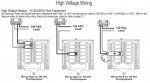
You can see in the omnilogic panel how the area to the left (low voltage) is separated by a metal divider from the area on the right (high voltage) - that's to prevent inadvertent shorting, etc., and likely meet the UL requirements.
So would it work? I believe so. Should you do it? I would not. There's usually a good reason for the codes, and saving a few dollars on the extra transformer is probably not worth the risk.
Of course I could be off the mark here, and maybe someone else will chime in with a different answer...