MaxFlo XL 1HP SP2307X102

caycarem

0
LifeTime Supporter
May 16, 2009
244
Pleasanton, CA
Re: 2 speed or not 2 speed?

hayward maxflo XL two speed pump arrived and it didn't come with a switch? i just found out my T104 timer will not work with it. can someone recommend an affordable timer to buy? could also use a guide/video on how to wire this. If i had known I'd gone for the variable speed w/ built in timer :(
thanks,
 
thank you for the SPDT suggestion I will get one of those! in the mean time I have tried to wire up the motor for low speed only through a T104 (dead motor) but it's not working.....can you take a look:
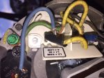
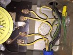
I think i have a 220V breaker, 2 yellow wires going to the T104, then 2 yellow wires from T104 going to the motor input "A" and "L2" (common). I turn the T104 switch on, both yellow wires are hot (i check the motor input there is voltage) what am I doing wrong?
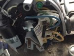
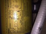
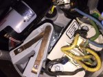
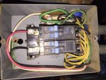
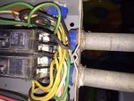
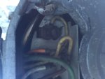
here are the pics:
image1.jpgimage2.jpgimage3.jpgimage4.jpgimage4.jpgimage5.jpg
 

Enjoying this content?

Support TFP with a donation.

Give Support
i tried to measure across the 2 yellow wires @motor or @T104 but it didn't have any voltage...then i checked across the red & black wires (from breaker) also no voltage, but there is 120v across red/white or black/white. i'm a bit confused now.
 
That is what I was thinking. I am wondering if that breaker panel is capable of a 240V circuit. Across the 2 yellow (assuming they were Line 1 and Line 2 of a 240V circuit) or across the red and black should measure 240V. The fact that you measured 0 means they are the same phase (like two Line 1).

So your Red and Black are being fed by the same phase from the main breaker panel. What do the bus bars under the breakers in that subpanel look like? I am going to assume that the Red wire only feeds the top breaker (tandem in this case) and the Black only feeds the bottom breaker (tandem in this case). With the rod between the 2 middle switches it tries to make a 240V circuit, but it appears that the connections of the red and black in the main panel are not correct.
 
what's a bus bar? what you said makes a lot of sense -but this seems strange, the setup has been like this for my old pump since forever which stopped running few weeks ago, same T104 with 2 yellow/1green wire going into the old motor that i removed as i assumed it broke. and i have no idea where the breaker's red/black wires are coming from, is it possible they don't come from the main house breaker panel? here's the old pump connection:
aquaflow-magnatek old pump.JPG
 
The wires supplying the sub panel must be coming from another breaker panel somewhere.

Did you add the black wire going to the motor? Was there only 2 yellow and a green before?

Given your questions, and the fact we are dealing with electricity, might be time to call in a professional. Clearly the sub-panel is not currently supplied with 240V and we can not easily figure out your setup over the internet.
 
the 2 yellow lines are wired to middle switches so it's trying to create 240V as you said. here's the old motor View attachment 34546

- - - Updated - - -

yeah i added the black wire to L1 so i could add a DPDT switch once it arrives. it's not being used at the moment.
The wires supplying the sub panel must be coming from another breaker panel somewhere.

Did you add the black wire going to the motor? Was there only 2 yellow and a green before?

Given your questions, and the fact we are dealing with electricity, might be time to call in a professional. Clearly the sub-panel is not currently supplied with 240V and we can not easily figure out your setup over the internet.
 
The way they have the breakers in the sub panel wired, it will supply 230 volts to the pump provided the yellow wires are running to the timer.

You should be able to read 230 volts between the red and black wires on top of the breakers. If you can't, I suspect that the breaker feeding this box is tripped. You need to find that breaker.

Also I don't personally like using a 3-way light switch to change the speeds on the pump. I like using a switch with a center off position.

Ok, I'm going to find that son of a ...breaker, i have yet to find it (house built 1966, main panel in garage, any other likely locations you think of for this mysterious breaker? going to check crawlspace next). though would they still have 125v on each of the red/black wires as i measured with the white wire, IF the originating breaker was tripped?
for the switch you mean a DPDT?
thanks for all your help everyone, it is much appreciated.
 
The fact that you are measuring 120V on the red and black with white indicates that the breaker feeding them is not tripped. The fact that you measure 0V between the red and black indicates that they are on the same phase (incorrectly wired at the source ... not sure how a bad breaker could cause this).

Dave is saying he prefers a DPST toggle switch that has an OFF in the middle for selecting the speeds. If you have the timer nearby, seems easy enough to throw that switch if you want it turned off and just use a regular DPST switch to pick the speed. Plus if you use a toggle with a off in the middle, you could turn that off and the pump would be off, but one leg of the power could still be live in the motor ... could be dangerous if you forget to turn off the breaker when doing any work.
 
Given that they rigged the "common" trip on the breakers in the sub panel with what looks like a piece of wire, I wouldn't be surprised if the one in the feeder panel was done the same way (or not even set up for common trip). If that's the case you could have one breaker tripped and one not, Which would allow you to read 120 volts to neutral from both the black and red wires, but not between them, due to it backfeeding through the timer/pump motor.

Once you find that feeder breaker you'll know more about what's going on.
 

Enjoying this content?

Support TFP with a donation.

Give Support
Thread Status
Hello , This thread has been inactive for over 60 days. New postings here are unlikely to be seen or responded to by other members. For better visibility, consider Starting A New Thread.