Electrical Question

MJCP

0
Sep 14, 2007
139
Michigan
My 1980's vintage pool wiring is in poor condition, and has had several questionable changes made by the previous homeowner.

The current configuration is as follows

Conduit running from panel in the house contains 7 wires
1 - Black (part of 220 line)
2 - Red (part of 220 line)
3 - White (part of 220 line)
4 - Green (part of 220 line)
5 - Black (120)
6 - White (120)
7 - Green (120)

The 120 line feeds to a GFCI breaker then a Switch (Black) then the pool light
The 220 line feeds one leg (Black) to the LINE 1 on an intermatic mechanical timer the other leg (Red) to LINE 2.
Load 1 on the timer and Load 2 feed to an old Side Mount box with 2 glass fuses one for each leg. then to a DPDT switch.
The DPDT switch feeds one line to the pump motor, the other leg to the Heater.
Effectively they are using the 220 line as 2 - 120 circuits.

I plan on replacing the Glass fuses and switch with a Pool/Spa breaker box w/gfci.

2 questions.
The Pool/Spa Boxes sold at the Big box stores all seem to be 50 or 60 amp. Yet my pump and heater are more like 15 amps. Why would I use such a large breaker when the load is expected to be 15 amps?

and - Can I safely continue using the 220 line as 2 separate 120 circuits

Thanks for your help.
 
Since the 220 line has four wires, you can use it to feed a sub-panel, and then run 115 volt lines off of breakers in the sub-panel. You shouldn't just wire it directly to two separate 115 volt circuits.

Sub-panels tend to have high ratings, but you don't need to use their full rating. You don't need to supply the sub-panel with a 60 amp breaker, nor should you since the wire is almost certainly not large enough. Nor do you want a 60 amp master breaker in the sub-panel.
 
My pool equipment is all run off a single 20amp 230V circuit that feeds a subpanel at the equipment pad. The subpanel then has a 230V circuit to the pump and a 115V circuit to a GFCI outlet which feeds the pool light.

I had an old 4 place round fuse panel, but now have a breaker panel in my ProLogic automation center and no longer use the fuses.

There are certainly many questionable things I have found ... joy of an older house. Like the 230v circuit in the main panel was feeding the subpanel with 2 separate 115V breakers :hammer: And there did not used to be any GFCI on the pool light. :shock:
 
Can you find out what gage wire is coming from the main panel on the 240 line? If we know what that is, then we can get that properly fused to protect a sub panel that should be out at the equipment pad. The sub panel then can be used to provide proper overcurrent protection to the equipment. also, Check the wiring to see if it THWN wire (should be marked on it)
 
The wire coming from the house is 12 gauge. I couldn't see any marking on the wires as to THWN or not, but I assUme wiring was to 1976-1978 code but no better.
I broke down and bought the Square D Pool/Hot Tub subpanel with 50 amp GFCI breakers (btw the 220v - 12 gauge line from the house comes off a 20 amp Breaker) .
After reading up I've decided to run the pump and heater at 220v instead of 110
The separate 120 Line coming from the house feeds a different GFCI Breaker in another box which goes through a switch then to the pool Light.

As I look at this layout I can see that the wiring is pretty straightforward. 220 feeds the subpanel Black White Red and green.

The Load side is Black Red and Green to the Intermatic Timer (No Neutral/White)
Pump Motor runs 220 Black Red Green
Heater runs 220 Black Red Green

So Why does code require a GFCI? It appears GFCI isn't functioning in this configuration since White(Neutral) never carries any current.
Am I missing something?

I know if I try tapping a 120 leg I will use the White and One of the Hot leads )along with ground, and then the GFCI WILL have current.

Thanks - Mike
 
Last edited:
I mean exactly what I said. Not sure how else to state it.

Technically you could leave the 50 amp breaker in the subpanel, but it will not do anything because you are feeding it from a 20 amp breaker in the main panel which will trip first.

Honestly, based on some of these questions, might be safer to hire someone.
 
By National Electric Code (NEC), 12 gauge wire has a maximum ampacity of 20 amps. Since you have a 20 amp breaker in the main panel feeding the sub-panel you must swap the 50 amp breaker in the Square D sub-panel for a 20 amp breaker. Better double check your local building codes as each locality can modify the NEC to be more restrictive.
 
By National Electric Code (NEC), 12 gauge wire has a maximum ampacity of 20 amps. Since you have a 20 amp breaker in the main panel feeding the sub-panel you must swap the 50 amp breaker in the Square D sub-panel for a 20 amp breaker. Better double check your local building codes as each locality can modify the NEC to be more restrictive.

The 50 amp can stay right where it is. As long as the 20 amp breaker in the main box is protecting the circuit, everything is fine. The 50 amp simply serves as a disconnect switch.
 

Enjoying this content?

Support TFP with a donation.

Give Support
The wire coming from the house is 12 gauge. I couldn't see any marking on the wires as to THWN or not, but I assUme wiring was to 1976-1978 code but no better.

We had a thread a while back where a pool owner had al kinds of problems with GFCI's tripping. turns out the wiring done prior to his owning the house was not done right. It took some time but he did discover that the wiring used was NMb (romex house wire) that is not rated for outdoor/wet location use. The wire you have, if it is a cable (2 or more wires in a sheath) should have a marking of some sort on it. When I asked about THWN I assumed this was in conduit. If it a sheathed direct burial wire it should be a grey colored sheath marked as UF. May say something like 12-2 UF 600 volt.


I broke down and bought the Square D Pool/Hot Tub subpanel with 50 amp GFCI breakers (btw the 220v - 12 gauge line from the house comes off a 20 amp Breaker) .
After reading up I've decided to run the pump and heater at 220v instead of 110
Should be usable. The 50 amp GFCI is a sit overkill for a disconnect switch on a 20 amp circuit. Each item in the box should have it's own GFCI breaker

The separate 120 Line coming from the house feeds a different GFCI Breaker in another box which goes through a switch then to the pool Light.
The GFCI for this could have been put in the main box. No problem with the setup as is
As I look at this layout I can see that the wiring is pretty straightforward. 220 feeds the subpanel Black White Red and green.

The Load side is Black Red and Green to the Intermatic Timer (No Neutral/White)
Pump Motor runs 220 Black Red Green
Heater runs 220 Black Red Green

So Why does code require a GFCI? It appears GFCI isn't functioning in this configuration since White(Neutral) never carries any current.
Am I missing something?

I know if I try tapping a 120 leg I will use the White and One of the Hot leads )along with ground, and then the GFCI WILL have current.

Thanks - Mike

a 240 circuit on a gfci does not use a neutral to monitor current loss. The monitoring of the current loss is based on the flow between the two legs of the circuit. You can not tap a 120 off of a 240 circuit that is protected by a gfci as the 240 gfci will trip as soon as the 120 load is turned on and current is sent down the neutral. This will cause an imbalance in the 240 circuit that the gfci will see. My suggestion would be to put two 15 or 20 amp single pole gfci breakers in the sub panel to feed the heater and the other 120 volt circuit with them.
 
Thanks for all the information and Help.
I have it all worked out and working now.

Just to clarify there were 2 lines coming in, a 220 and a separate 120 from the Main. I had not planned to tap the 220 for a 120 leg, I was just asking if my logic was correct, that the 220 Which doesn't use a neutral would work as a GFCI protected circuit.

My cable in the conduit - Further inspection shows this is actually a Flat Grey UF Cable Buried underground, the "conduit" only carries the wire from just underground, through the conduit into the subpanel about 3 1/2 ft total.

Thanks again - The advice in these forums is the best of any forum on the net.
 
The 50 amp can stay right where it is. As long as the 20 amp breaker in the main box is protecting the circuit, everything is fine. The 50 amp simply serves as a disconnect switch.

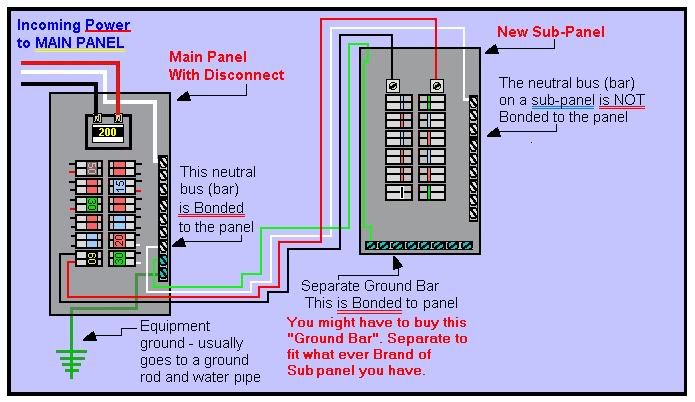
I would like to note that if you are creating a subpanel the code requires that in the subpanel. the neutrals and grounds may NOT share the same bus and must be seperated. You nee to remove the bonding screw in the new subpanel
 
I would like to note that if you are creating a subpanel the code requires that in the subpanel. the neutrals and grounds may NOT share the same bus and must be seperated. You nee to remove the bonding screw in the new subpanel

Correct. The ground bar in a sub panel HAS to be bonded to the box. The neutral is to be isolated (floating) from the ground system.

Here is a good illustration of a sub panel setup
 
Thread Status
Hello , This thread has been inactive for over 60 days. New postings here are unlikely to be seen or responded to by other members. For better visibility, consider Starting A New Thread.