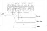
Detail on wiring Pump/Stenner to P1353 ME timer

Your wiring diagram is very reasonable. Note that it may not be practical/safe to fit four wires on one terminal. Depending on how things fit you may need to run a short wire to a wire nut with some of the wires that would otherwise go to that terminal.
 
Your wiring diagram is very reasonable. Note that it may not be practical/safe to fit four wires on one terminal. Depending on how things fit you may need to run a short wire to a wire nut with some of the wires that would otherwise go to that terminal.

Good Point...wonder if there is room in box for a small terminal black? Likely not...


... And keep in mind that all of the L2 are always hot.

Is this an issue for any reason? From what I seem to recall w/ current T104 timer, both heater and pump have L2 wired to always hot terminal...but I could be wrong, happens often!
 
Modern practice is to switch both legs of a 230 volt circuit whenever possible. Otherwise you will have voltage present inside the motor even when it is turned off. It won't use any electricity, it is more of a "accidentally get electrocuted when poking the motor with a screwdriver in ways you shouldn't even when it is actually off" kind of risk. Switching both legs is not required by code and is frequently not done.

The P1353 has the option to switch both legs of one circuit, and only a single leg of a second circuit. When used in that mode it loses it's ability to control three circuits, and is limited to two.

Looks like Mode 5 is that option; only limitation is Circuit 3 independent of 1/2 so, theoretically, if timer got messed the Stenner could turn on without the main pump being on. Likely never happen unless timer itself goes wonky...providing timer window for 3 is contained within timer window for 1/2 which is really just a programming item.

Probably going with initial diagram above, only change being pigtail L2 for stenner off of heater L2 as both will be running into junction box so Stenner outlet/receptacle wires can run into main timer box in same Liquidtite run as heater.

Now if I could just get some time off work at pool company to hook it all up; busy season still very busy. Funny, when I worked as a software developer I had plenty of free time at work to cruise pool forums; now, working for a pool company, when pool forums like this would actually be 'work-related', I got no time to read them. Careful what you wish for.:confused:
 
Thread Status
Hello , This thread has been inactive for over 60 days. New postings here are unlikely to be seen or responded to by other members. For better visibility, consider Starting A New Thread.