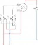
Current Sensor/relay switching for SWG

acamato

0
LifeTime Supporter
May 12, 2008
153
Long Island, NY
I have a EcoTech VS motor on a Hayward SuperPump. The motor is directly wired to the breaker in my pool panel. My SWG is also wired to a breaker in my pool panel. I was relying on the flow switch to stop the SWG from generating. I have been getting errors on the SWG after the pump turns off. If I start the pump and cycle power on the SWG, the errors go away. I needed a solution to switch the SGW with the pump.

I got my idea from this thread: http://www.troublefreepool.com/thre...rol-IntelliChlor-IC40-w-Current-Control-Relay and thins book: http://books.google.com/books?id=2q...DZgc#v=onepage&q=dust collector relay&f=false

I have ordered the following:

The current sensor is self powered so it doesn't need external power.

I will update the thread when I get the items in and installed.
 

Attachments

  • Current Relay.jpg
    Current Relay.jpg
    23.5 KB · Views: 407
I don't think your connections are right. Try connecting one side of the contact from the current sensing relay to terminal 2 of the power relay. The other side of the contact from the current sensing relay should then connect to terminal 0 of the power relay. Terminal 1 of the power relay should then be jumpered to terminal 6.

That will put the contact of the current sensing relay in series with the coil of the power relay. When the contact closes, the coil will energize and close the contacts between 2 and 4 and between 6 and 8. The way you have it, the contact will just short out the coil.

terminal 0 and1 are for the coil for the relay. 2,4,6 and 8 are the switched contacts.
When the pump is running it will induce a current in wires from the current sensor. This induced current will be enough the energize the coil of the relay and close the contacts, completing the power circuit for the SWG.

Sent from my GT-N5110 using Tapatalk
 

Enjoying this content?

Support TFP with a donation.

Give Support
The sensor and relay were delivered. I just need to find the time to install and wire them up. My priority is getting a bottom body for my Micro-Clear DE filter. I guess I didn't drain it completely this winter and it has a crack in the bottom. I found a used one on craigslist for $55, going to pick it up tonight. It is a re-branded (Leslie's Pool) Micro-Clear.
 
Update: The current sensor is not self powered. It is a current switch. (I was looking at so many current sensors and I must have gotten confused)

Solution: Install a 120V to 24V transformer in the current switch/relay coil circuit.

I placed an order for a transformer http://www.functionaldevices.com/building-automation/display.php?model=TR20VA001

It was $6.81 from zoro.com.

Total for parts: $30.06.

I will update the wiring diagram and original post when I get it working.
 
I finally got around to installing this 2 years later. I got the transformer, relay and current switch installed this past weekend. The current switch has to low of a trip. My pump draws 0.4A when it is off in each leg. The current switch trips at 0.25A. I ordered a RIBXKTA switch. It has an adjustable trip set point. It will be delivered tomorrow.

This is what I ordered: Functional Devices, Inc. - Products - Building Automation - Current Sensors - RIBXKTA

Do you know why your pump draws 0.4A when it is off in each leg? It should be close to 0A, right?
By the way, why not use the current switch only? There are some current sensing switch allows up to 2.5A output current.
 
I assume the power is used for the motors controller. I needed to use a relay to switch the SWG. The SWG is 240V. The current switch will not switch 2 120v lines and it is not rated for the current the the motor draws.


Sent from my iPhone using Tapatalk
 

Enjoying this content?

Support TFP with a donation.

Give Support
Thread Status
Hello , This thread has been inactive for over 60 days. New postings here are unlikely to be seen or responded to by other members. For better visibility, consider Starting A New Thread.