Open up the junction boxes outside and see what type of wire is in them. The wires in the boxes should be either a grey sheathed romex type of cable with the letters UF stamped on them somewhere or individual wires with THWN stamped on them. Both of these are rated for wet location (underground/outdoor) use. If it is not either of these you may be looking at having to pull the wires and replace them. A lot of times people mistakenly pull type NM romex into conduit thinking that it will stay dry. It won't and will eventually deteriorate the insulation on the wires.

Another GFCI circuit breaker question
- Thread starter myrddin
- Start date
You are using an out of date browser. It may not display this or other websites correctly.
You should upgrade or use an alternative browser.
You should upgrade or use an alternative browser.
I'm barely a DIY electricition, but I'm not sure it's Kosher to have white wires connected to a breaker. Be careful when you're working with that stuff.
The white wire going to the GFCI in the breaker box is how the breaker determines the current in-vs-current out measurement. If the differential goes beyond the trip rating (4-6 milliamps) then the device will stop power flow
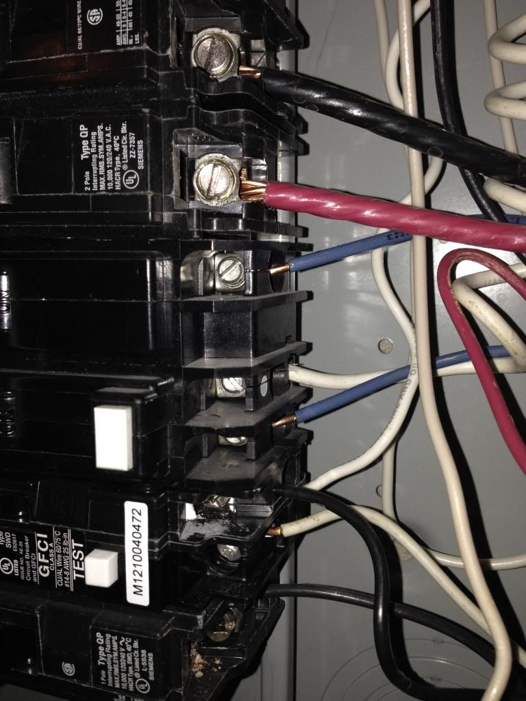
In the second picture I see 2 GFCI breakers. One with a black wire and one with what looks (to these colorblind eyes) like a blue wire. I see a neutral wire going to the lower breaker with the black wire. I do not see a neutral wire going to the upper breaker with the blue wire. Which of these breakers is the one tripping, and which one controls what for the pool? I am assuming both go to the poolI went back down to the box in my basement to get a good idea as to how they hooked it up. Keep in mind that when I turn on the light with the wall switch it trips, but I can turn the breaker back on and it's fine, in fact as far as I know if I left the light switch on I could turn the lights off and on at the breaker with no problem (worth a test).
Wiring goes as follows:
Three wires that run outside to the equipment pad:
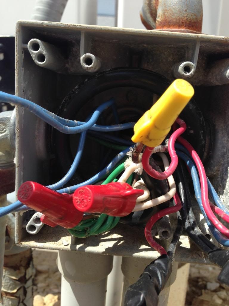
Red (goes to a yellow wire nut that has a black wire that goes into the wall to the switch I think).
Black (goes to a yellow wire nut that has another black wire going to the gfci and also a white wire that goes into the wall (to switch I think).
White (goes to the gfci)
The wire that feeds the switch has a copper wire that goes to the neutral bar
I can't see a ground for the red/black/white wire that runs outside. But it might be there (will look better in the morning)
The pool light is in the same circuit so to meter the retaining wall lights I think I need to do it at the junction box at the pool pad... But I guess I can pull the swimming pool light and remove that bulb too? Might be good to meter the whole circuit first at the breaker box, then if it shows other than infinite (it will beep in my case) I can then go do the same at the junction box on the equipment pad...
Thoughts?


You mentioned in this post that there is a red (not sure of it's source) a black (assuming it is one of the GFCI's) and a white. This is a classic indication of a multi-wire branch circuit. This type of circuit has two hots that share a neutral. This can not have GFCI breakers on it
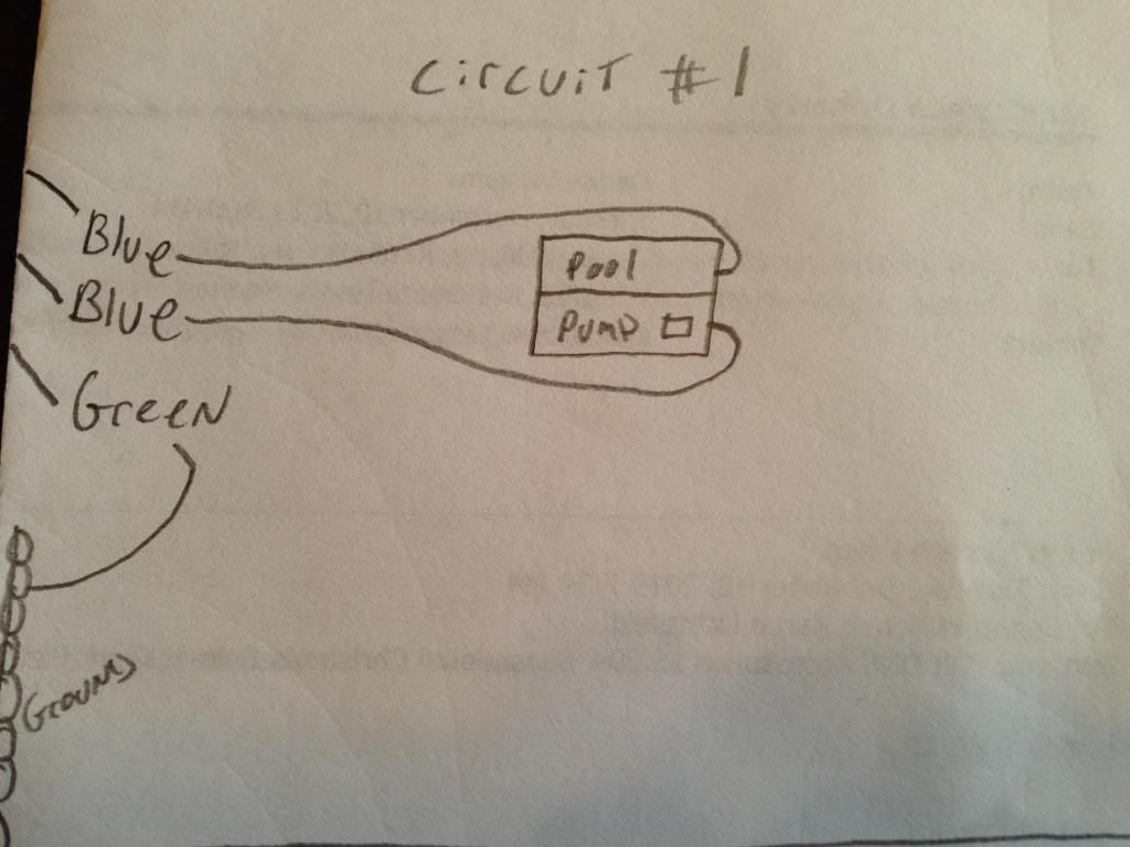
The 2 GFCI's are both for the pool... Top one is for the pump (not sure what else need to look it over - will do that today as well) but the blue wire in this case is the neutral wire (will get back on what goes where.
the bottom of the two is the one that is tripping, the red, black, white wire is the one that goes from the breaker box (in my house) to the equipment pad. you say it cant have a GFCI on this circuit I want to be clear so I understand...
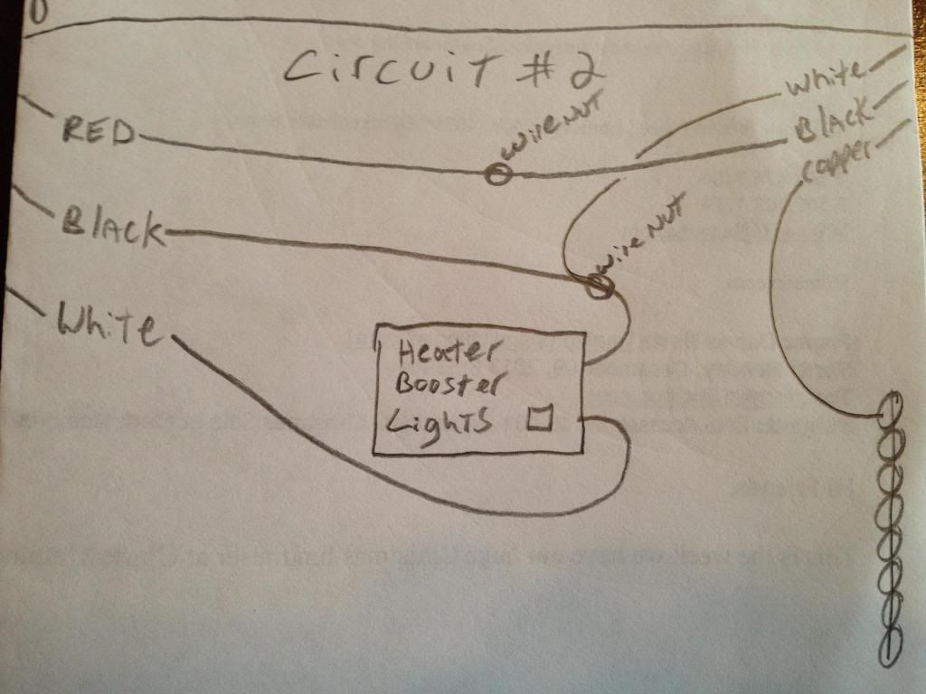
that red/black/white wire does feed two circuits:
1. a switched wire from my house to the lights.
2. a switched wire to the booster pump at the pad.
3. a switched wire to the heater at the pd.
Three wires that run outside to the equipment pad:
Red (goes to a yellow wire nut that has a black wire that goes into the wall to the switch I think).
Black (goes to a yellow wire nut that has another black wire going to the gfci and also a white wire that goes into the wall (to switch I think).
White (goes to the gfci)
so for clarity I have the one breaker in this circuit, it is tied to a wall switch (that is inside the house)then it goes out the house, in the ground to the equipment pad at a junction box. There its split off for the lights, the booster pump, and the heater... (heater and booster pump have their own switch at the pad).
coming back with more info on the first gfci, but it never trips...
Update:
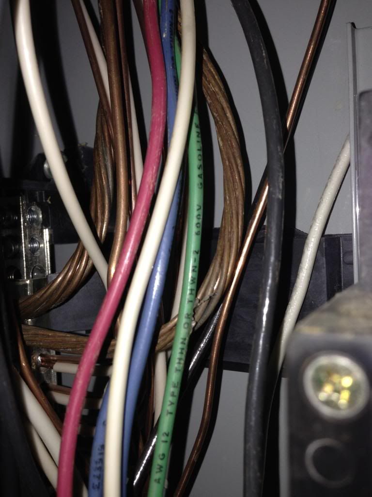
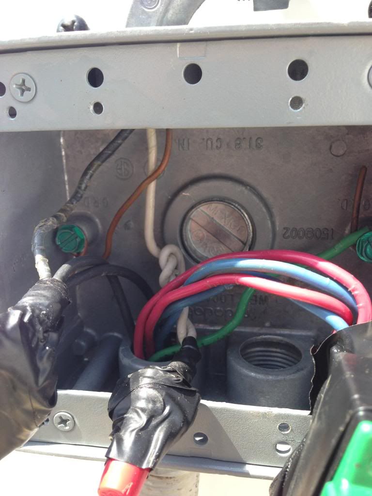
also running out to the pad is a Blue, Blue, Green wire (all these wires say THWN) this is the 230 or whatever circuit for the Pump...
Green runs to the ground bar
Blue runs to the breaker
Blue runs to the breaker

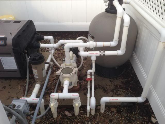
Also this might help better than words:
I will get into the junction box later today.
the bottom of the two is the one that is tripping, the red, black, white wire is the one that goes from the breaker box (in my house) to the equipment pad. you say it cant have a GFCI on this circuit I want to be clear so I understand...
that red/black/white wire does feed two circuits:
1. a switched wire from my house to the lights.
2. a switched wire to the booster pump at the pad.
3. a switched wire to the heater at the pd.
Three wires that run outside to the equipment pad:
Red (goes to a yellow wire nut that has a black wire that goes into the wall to the switch I think).
Black (goes to a yellow wire nut that has another black wire going to the gfci and also a white wire that goes into the wall (to switch I think).
White (goes to the gfci)
so for clarity I have the one breaker in this circuit, it is tied to a wall switch (that is inside the house)then it goes out the house, in the ground to the equipment pad at a junction box. There its split off for the lights, the booster pump, and the heater... (heater and booster pump have their own switch at the pad).
coming back with more info on the first gfci, but it never trips...
Update:
also running out to the pad is a Blue, Blue, Green wire (all these wires say THWN) this is the 230 or whatever circuit for the Pump...
Green runs to the ground bar
Blue runs to the breaker
Blue runs to the breaker


Also this might help better than words:


I will get into the junction box later today.
The 2 GFCI's are both for the pool... Top one is for the pump (not sure what else need to look it over - will do that today as well) but the blue wire in this case is the neutral wire (will get back on what goes where.
the bottom of the two is the one that is tripping, the red, black, white wire is the one that goes from the breaker box (in my house) to the equipment pad. you say it cant have a GFCI on this circuit I want to be clear so I understand...
OK, I did not realize that the pool pump is a 240 circuit. The blue wire is not a neutral, there is no neutral in that circuit. That GFCI is not important in this conversation and the way it is wired it looks OK. The white pigtail wire from that breaker is there so the test button works.
In the pictures of the breakers I see (not counting whites), from the bottom going up, a black, a black then the two blues. I do not see where the red wire comes into play. I assume it is not the heavy #8/10 wire above the blue ones. What breaker does the red originate from? I see it floating around in one of the pictures but don't know where it originates from.
that red/black/white wire does feed two circuits:
1. a switched wire from my house to the lights.
2. a switched wire to the booster pump at the pad.
3. a switched wire to the heater at the pd.
Lets try to look at where the wires came from at this point, not where they go to. In other words, you say there is three wires going out to the equipment pad, red, black and white. The white is the neutral in this circuit and appears to be landed properly on the GFCI. I also see the black coming from the GFCI. The red is the question and I think may be the source of the problem.
Edit: I looked at a different picture and see the red & black under the yellow wire nut. Looks like the red goes out to the equipment pad and the black is fed from higher up in the box. According to what you said there is, going out to the pad, a black, a red, and a white. I now fully believe the problem is that there are two hots being served by one neutral. With a GFCI in the circuit you will need separate neutrals for each hot. There are also some minor code violations regarding that multi-wire branch circuit as well.
Three wires that run outside to the equipment pad:
Red (goes to a yellow wire nut that has a black wire that goes into the wall to the switch I think).
Black (goes to a yellow wire nut that has another black wire going to the gfci and also a white wire that goes into the wall (to switch I think).
White (goes to the gfci)
so for clarity I have the one breaker in this circuit, it is tied to a wall switch (that is inside the house)then it goes out the house, in the ground to the equipment pad at a junction box. There its split off for the lights, the booster pump, and the heater... (heater and booster pump have their own switch at the pad).
The top breaker looks fine as it is wired. The wire, THWN is proper for the use, and whoever wired it did a good job. We don't need to worry ourselves with that circuit anymore.
coming back with more info on the first gfci, but it never trips...
Update:
also running out to the pad is a Blue, Blue, Green wire (all these wires say THWN) this is the 230 or whatever circuit for the Pump...
Green runs to the ground bar
Blue runs to the breaker
Blue runs to the breaker
I will get into the junction box later today.
In the pictures of the breakers I see (not counting whites), from the bottom going up, a black, a black then the two blues. I do not see where the red wire comes into play. I assume it is not the heavy #8/10 wire above the blue ones. What breaker does the red originate from? I see it floating around in one of the pictures but don't know where it originates from.
that red/black/white wire does feed two circuits:
the red wire that runs to the pad is connected to the black wire that runs to the light switch area. in that diagram on circuit #2 the white, black, copper go to the wall switch for the lights.
Lets try to look at where the wires came from at this point, not where they go to. In other words, you say there is three wires going out to the equipment pad, red, black and white. The white is the neutral in this circuit and appears to be landed properly on the GFCI. I also see the black coming from the GFCI. The red is the question and I think may be the source of the problem.
I will go open the junction box in a few... (look for an update)
I am unsure about the two hots and one neutral how can I show you so we know for sure?
going out to the pad for pics of the junction box now..
Can I suggest that you use standard conventions of describing electrical wiring to help us understand your wiring. Electricity usually flows from a source, through a circuit breaker and then to the load. When you say a "blue wire runs to the breaker", what I think you should say is a "blue wire runs from the breaker" (and then to the pump). Some of your descriptions are correctly stated, some are not and it makes it difficult to follow. Hope you take this as constructive, as it's meant.
You mention at one point that the blue wire for the pump is a neutral. Not sure if you mean one or both. In any case I don't think that is correct. I suspect you have a 220V pump motor which would mean there is no neutral at all, just 2 power wires (and hopefully a green safety ground wire too).
Your drawings are helpful but it would be good if you show where the wires that are going off the page are believed to be coming from or going to. Again, try to describe in terms of the direction of electrical flow from source, to load.
It looks to me that the black is a hot to the pad, and the white is the neutral to the pad. The red is a switched hot to the pad. I'd assume the black is for the booster pump and the red is for the lights, and that they are served by a single neutral.
To be "right", you should add a circuit and run a separate hot, neutral and ground to the pad for your booster pump and leave this one dedicated to the lights, though you probably shouldn't have anything else on the circuit with the pool light since code requires a continuous ground from the panel.
To be "right", you should add a circuit and run a separate hot, neutral and ground to the pad for your booster pump and leave this one dedicated to the lights, though you probably shouldn't have anything else on the circuit with the pool light since code requires a continuous ground from the panel.
the red wire that runs to the pad is connected to the black wire that runs to the light switch area. in that diagram on circuit #2 the white, black, copper go to the wall switch for the lights.
OK, then that explains the white wire under the white wire nut with the two blacks hooked to it. The white is the power feed to the switch and al least should have a piece of black tape on it to indicate it is a hot wire. This rules out the MWBC theory I had.
OK sorry I will try harder to make it sound more standard... I am back from the pad and its going to take me some time to test out which on goes where... been a while and I dont remember...
that being said I will show what little I can tell at a glance.
the round black coated wire is the pool light (Green, Black, White)
looks like all greens are combined to make up the ground, and all white are combined to make up power... I know I need better pics, I will work at a bigger diagram too...
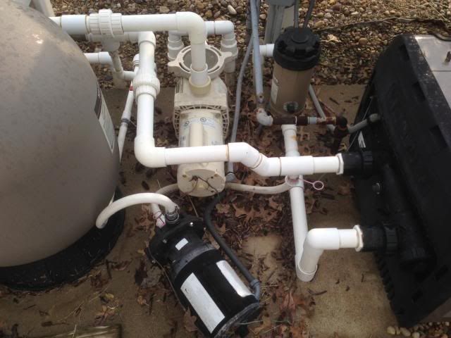
Junction box
Switches for pump and heater
Switch for booster pump:
Working on diagram to show what I know...
that being said I will show what little I can tell at a glance.
the round black coated wire is the pool light (Green, Black, White)
looks like all greens are combined to make up the ground, and all white are combined to make up power... I know I need better pics, I will work at a bigger diagram too...
Junction box

Switches for pump and heater

Switch for booster pump:

Working on diagram to show what I know...
OK sorry I will try harder to make it sound more standard... I am back from the pad and its going to take me some time to test out which on goes where... been a while and I dont remember...
that being said I will show what little I can tell at a glance.
the round black coated wire is the pool light (Green, Black, White)
looks like all greens are combined to make up the ground, and all white are combined to make up power... I know I need better pics, I will work at a bigger diagram too...
Switch for booster pump:
Working on diagram to show what I know...
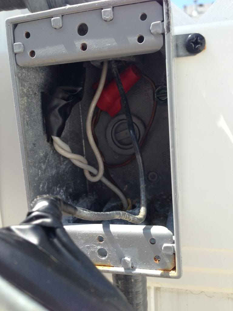
In this picture, it looks like there is a romex type of cable sheathing peaking out of the top of the conduit in the bottom of the box. We need to determine if that is wet location rated wire. This whole circuit (panel to junction boxes) is a bit suspect to me as it looks like whoever did the work in there was not a qualified electrician. If I were working on this I would be concentrating on deteriorated wiring as the culprit.
that romex runs to the booster pump (its not underground, and the pump is a few feet from it), which has its own switch as you see there... I can turn it on/off with no trouble... same for the heater. I am trying to figure out how to show you folks what is there... its tough since there are so many wires. This was installed when the house was build about 10 years ago... I am second owner so who knows?
one thing I will say, is that the heater and booster are on the same circuit and I can operate them without fail... I only trip the breaker when I turn on the lights from the wall switch. And still, if I flip the breaker back on after, it will stay on.
old pic
one thing I will say, is that the heater and booster are on the same circuit and I can operate them without fail... I only trip the breaker when I turn on the lights from the wall switch. And still, if I flip the breaker back on after, it will stay on.
old pic


OK, I know this is not what you would expect, but I'm trying... Here is a hand drawn diagram... I can see more or less what the lines are connected to now.
Sorry I cant get this any cleaner:
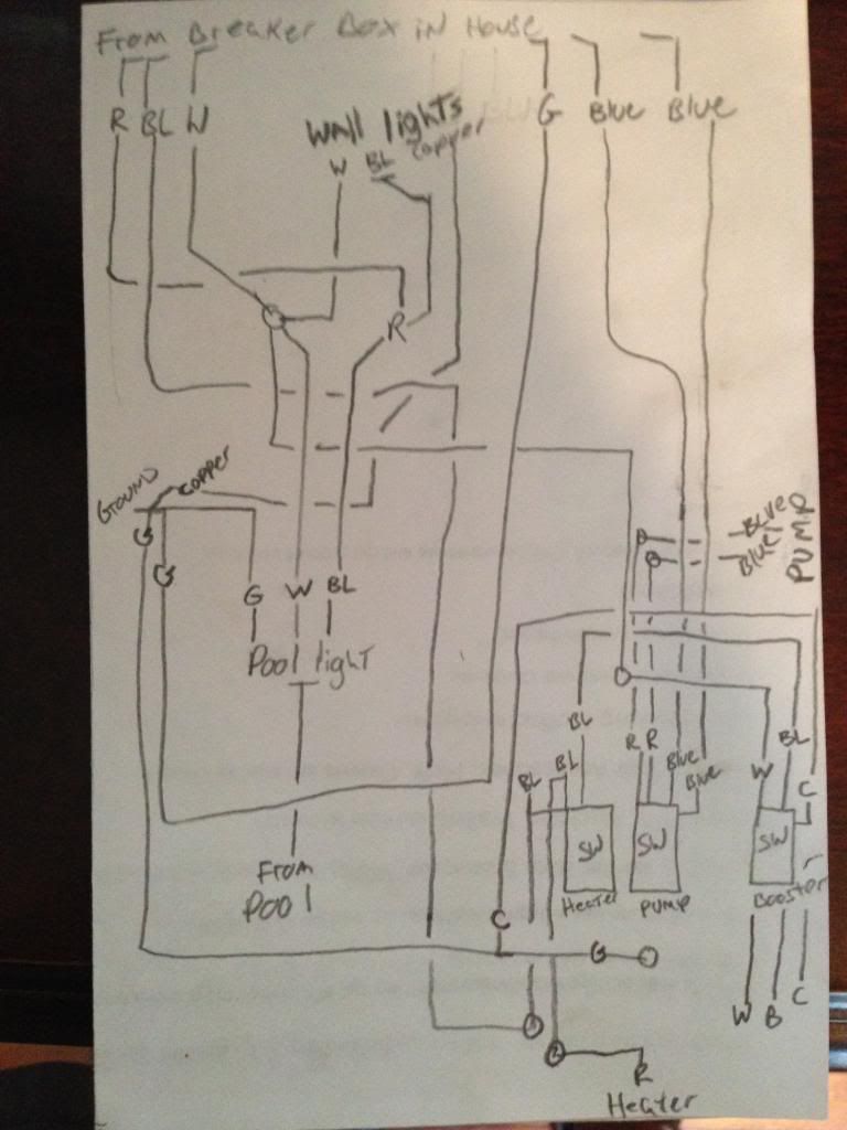
Sorry I cant get this any cleaner:

I went back and removed the white and black wires for the wall lights... Do I need to remove the ground as well to test the resistance? Also I am not sure my meter is working... I have a Mac Tools meter with an Ohms setting (it will do auto for the range... I cant get it to read anything when I test... If I switch it to DWL for the ground fault beep I get no beep... I want to be sure I am testing right... I also have a cheap meter with Ohms setting (20M, 200K, 20K, 2000, 200) I tried it set to each one as well with no reading... Black lead to ground, red to the white wire. I have no bulbs in the fixtures. Right now the wall lights have been removed from the circuit and I am seeing if it still trips the breaker... I flipped it off and on about 30 times and it didnt trip... but sometimes it fools me and works till it dont... I will try it a few more times after work. After I can take the pool light off and just hook up the wall for another test?
Ground to black wire for the wall lights:
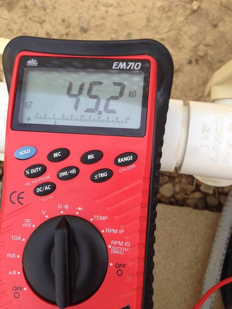
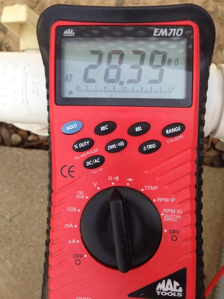
Ground to white:
Ground to black wire for the wall lights:

Ground to white:

The problem with using a conventional ohm meter is that it may not be sensitive enough to pick up the small amount of leakage that can cause a ground fault trip from insulation that is starting to break down. Hence my mention above of needing an insulation test meter or megger to rule out insulation break down. This is not to say it is not worth trying, but don't assume that if the wire passes this ohm meter test that it is good.
Ike
Ike
thanks Isaac-1 ... I put it all back together for the day. I removed the ground and the black and white wires for the retaining wall lights. I will keep them disconnected for now while I look at this resistance deal, but I did cut and clean the Pool Light wires and re join them... I might like to clean the copper too as I fool with all this. What do you think with my results? I guess what I meant above is that I was expecting 1 ohm or at least less than 5 to show up... I need to find another thing to test so I know my meter is giving a good reading...
Sometimes the light just works fine for hours at a time, so lets see what it does with the retaining wall disconnected for a day or so. If it trips as is, the wall lights may not have anything to do with it.
Sometimes the light just works fine for hours at a time, so lets see what it does with the retaining wall disconnected for a day or so. If it trips as is, the wall lights may not have anything to do with it.
It looks like the Ohm meter is working. To test it, just touch the two probes together. You will get a tone which indicates that there is zero resistance. I agree with the above poster as far as getting any useful results testing the resistance this way. Bad wire insulation needs to me tested with a megger (megohmmeter) This device charges the line with a very high voltage and then detects if it is leaking off. The divide and conquer method you are using is the way I would go about this. Now that you have somewhat determined that it may be the wall lights, hook them back up and unhook the others and see what happens. If the results are what you were getting before then it is time to start looking at the wiring and see if anything is out of the ordinary.
Did you get a chance to see what type of wire is in that circuit?
Did you get a chance to see what type of wire is in that circuit?
All the wire is the thwn wire except the wire running to the booster pump (above ground wire). And I think the wall lights might not be then as well (trying to tell but looks like normal romex white/black/copper) I can't make out words. I do not get a beep when I check the wires for a short, but the resistance reads odd I think.. Wonder if home depot has a megger for rent?
My suggestion, hire an electric company that does work for a pool builder in your area. Have them come out and find out what's wrong. With the number of man hours you are spending and writing here you could have had this issue resolved. I know it's hard to let some things go to a professional and pay money to get it fixed, at least you can hopefully know it's done right and your problems are over. Plus they have the tools and the knowledge to resolve it for you. You could also learn from them and know what to look for down the road when or if this issue rises again.
I am sure there are places that you can rent meggers / insulation test meters, but I doubt Home Depot is one of them. Working used ones do show up on ebay though, sometimes selling in the $50-$100 range for more basic older models with out dated calibration. In this case I suspect you would want one that would test in either the 500 or 1,000 volt range, and a basic analog crank model would probably tell you enough information for a pass / fail indication. Just be ware meggers can be dangerous to operate due to their inherent shock hazard. The bigger issue may be trying to correctly interpret the readings, particularly if you have a marginal failure case. I can't comment too much here, as my experience with them does not involve household style wiring, but rather motor / generator windings.
Ike
Ike
Thread Status
Hello , This thread has been inactive for over 60 days. New postings here are unlikely to be seen or responded to by other members. For better visibility, consider Starting A New Thread.