
I FINALLY got my SWG installed and running
- Thread starter timerguy
- Start date
You are using an out of date browser. It may not display this or other websites correctly.
You should upgrade or use an alternative browser.
You should upgrade or use an alternative browser.
On CYA, that sounds like testing error, though it is impossible to know for sure. The next time you do the CYA test, try pouring the sample back into the mixing bottle and then repeating the filling of the view tube a couple of times and see how consistently you get the same reading. Also, indirect full sunlight is very important to get consistent results. This test gets easier and more consistent with practice.
Thanks Jason! I'm picking up a 6.5 lb bottle of AQUA CHEM MY SALT POOL SALTWATER STABILIZER at wallyworld since I needed to raise it some anyhow.
First full day numbers after replacing the capacitor this morning ")
FC-- 4.0 If I'd have run a FC test this morning, I'd be willing to bet it was 3.0-3.5, but I was in a hurry to get the capacitor installed!!
Cc--0
PH--7.8
TA--80
CH--90
CYA--60 Thank goodness it's back to 60 That was driving me nuts!
Salinity--Average 2400 Not accurate since hasn't run 24 hrs Instant 4400 Taylor 1766 Test kit--4100
Water temp--66
FC-- 4.0 Think I may have been off .5 yesterday
Cc--0
PH--7.8
TA--80
CH--90
CYA--70
Salinity--Average 3400 Instant 4300 Taylor 1766 Test kit--4000
Water temp--66
Cc--0
PH--7.8
TA--80
CH--90
CYA--70
Salinity--Average 3400 Instant 4300 Taylor 1766 Test kit--4000
Water temp--66
FC-- 4.0 Replacement system didn't generate any chlorine to speak of today. They received my original and ran tests on it and it was working just fine so they're sending it back to me I have to admit it was generating Chlorine just fine--my only real concern with it was the 4700 ppm instant salinity level it was reporting . Seems my timer was pulling 120 24hrs a day and DSP said it might have screwed up the system. They had me jumper it to 110 and change the wiring to the timer so it only has 120 v switched, previously, (the box) was having 110 on it the 16 hrs the 240 was off. But it has been stopping generation after about an hour and not starting back up again.
Cc--0
PH--7.8
TA--90
CH--90
CYA--80
Salinity--Average 3400 Instant 0000 Taylor 1766 Test kit--4200
Water temp--68
Cc--0
PH--7.8
TA--90
CH--90
CYA--80
Salinity--Average 3400 Instant 0000 Taylor 1766 Test kit--4200
Water temp--68
I don't know if you want to pursue this or now, but the statement "Seems my timer was pulling 120 24hrs a day and DSP said it might have screwed up the system." doesn't quite make sense to me. It sounds like it might not matter at this point, but if you feel like it, could you say more about that?
Sorry, but I didn't see this until just a while ago. You need to see what my timer wiring looks like. I'll pm you in the morning with a pic, and maybe have you call me to discuss it.
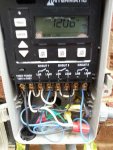
I have attached the picture you sent of your timer wiring.
It looks like you have an Intermatic P1353 timer, which has three single pole switches. These timers have several different ways they can be setup. Based on your previous comments I have a guess at what may have happened.
It is fairly common to have the P1353 setup to only switch one leg of 240 volt power (which has two hot legs). That means there is 120 volts present (relative to ground/neutral) on one of the two hot wires going to the pump and/or SWG. It is always better to switch both legs of 240 volt power, so there is no voltage present at the device when it is off. However, this is not always possible with a P1353 (depending on mode and other devices connected).
If you had it setup that way, only one leg switched, their comment/complaint sort of half makes sense. However, this is more of a long term safety issue than a day to day risk. There has to be something else fairly serious wrong before that can make any difference at all. When only one leg of a 240 supply is live, the only way for current to flow is for there to be a short between the other leg and ground/neutral. And if that were the case the circuit breaker would blow any time the device was fully turned on
Assuming I am not way off, I did some guessing here, then their claim that this could have damaged the SWG is ridiculous. I figure they are grasping at straws. Something is going wrong that they don't understand, and they are following up on something trivial that couldn't actually be the cause because they don't have anything else to follow up on. Having done a lot of tech support I sympathize with them. Figuring out tricky problems remotely is not always at all easy. Often, following up on something that is only kind of strange, rather than actually wrong, reveals the information you need to solve the problem.
Anyway, the short version of this long story is that the voltage/wiring issue referred to almost certainly has nothing to do with the rest of what is going on. There is a minor safety issue here, and their new wiring proposal is better, but I can't see any way it could have anything to do with any of your other issues. All assuming I haven't completely mis-interpreted some slightly cryptic comments you made/passed on.
Attachments
As far as I know, there isn't any way to switch both legs with this timer. With just the pumps, there isn't any problem since the constant 120 won't hurt them. But the SWG having constant 120 into the system "They" say confuses the software in the box and could have damaged it maybe set its internal clock off? I don't know. All I know is the second system that is now "running" stops generating after an hour or two, and doesn't come back on. All the other readings are shown, but there's no cell voltage or amps and 0 production and instant salinity is 0000 also. This morning 10 minutes after it started, it was doing fine, but now, and hour later, it has stopped generating chlorine.The first one just showed 6-700 ppm salinity higher than my Taylor-1766 was telling me. It always was generating though. I had a check salt flashing now and then, but the generator was still producing chlorine 80% of the time. They ran comprehensive tests on it yesterday and found nothing wrong with it, so they're sending it back to me and including a prepaid UPS label. Since that system was always wired as you see, evidently it didn't hurt the control box or cell. That doesn't make much sense to me. On the other hand, the system now running experienced the capacitor problem on my filter pump and had a no flow light on because the pump wasn't running for who knows how long last week. I'm wondering if THAT might have caused the problem I'm now having? I've got to chauffeur my wife around the rest of the morning.I have attached the picture you sent of your timer wiring.
It looks like you have an Intermatic P1353 timer, which has three single pole switches. These timers have several different ways they can be setup. Based on your previous comments I have a guess at what may have happened.
It is fairly common to have the P1353 setup to only switch one leg of 240 volt power (which has two hot legs). That means there is 120 volts present (relative to ground/neutral) on one of the two hot wires going to the pump and/or SWG. It is always better to switch both legs of 240 volt power, so there is no voltage present at the device when it is off. However, this is not always possible with a P1353 (depending on mode and other devices connected).
If you had it setup that way, only one leg switched, their comment/complaint sort of half makes sense. However, this is more of a long term safety issue than a day to day risk. There has to be something else fairly serious wrong before that can make any difference at all. When only one leg of a 240 supply is live, the only way for current to flow is for there to be a short between the other leg and ground/neutral. And if that were the case the circuit breaker would blow any time the device was fully turned on
Assuming I am not way off, I did some guessing here, then their claim that this could have damaged the SWG is ridiculous. I figure they are grasping at straws. Something is going wrong that they don't understand, and they are following up on something trivial that couldn't actually be the cause because they don't have anything else to follow up on. Having done a lot of tech support I sympathize with them. Figuring out tricky problems remotely is not always at all easy. Often, following up on something that is only kind of strange, rather than actually wrong, reveals the information you need to solve the problem.
Anyway, the short version of this long story is that the voltage/wiring issue referred to almost certainly has nothing to do with the rest of what is going on. There is a minor safety issue here, and their new wiring proposal is better, but I can't see any way it could have anything to do with any of your other issues. All assuming I haven't completely mis-interpreted some slightly cryptic comments you made/passed on.
That timer can switch both legs of a single 240 circuit using mode 5, however that uses two of the three slots, limiting how you can use the timer.
I've never worked directly with the model you have, so I don't know it's quirks, but it is common for amps, volts, and instant salinity to all be zero when the SWG is not trying to produce chlorine. This can happen for a couple of reasons, the most common being the off periods that occur occasionally when the percentage is set below 100%.
There does seem to be some kind of problem, I just can't see it having anything at all to do with the timer.
There is probably no way to tell at this point, but there may have been an electrical surge that damaged both the motor capacitor and the SWG. While possible, that seems unlikely as a surge normally either wipes out the SWG completely or does not affect it. The combination of symptoms you are seeing sound more like a software error or a misunderstanding of some mode setting rather than the result of surge damage.
That is just nonsense. Unless there is a short somewhere inside the SWG turning off one leg is sufficient. Even though the other leg is still live, there is nowhere for the current to flow and the SWG will be powered down the same as if you turned off both legs.But the SWG having constant 120 into the system "They" say confuses the software in the box and could have damaged it maybe set its internal clock off?
I've never worked directly with the model you have, so I don't know it's quirks, but it is common for amps, volts, and instant salinity to all be zero when the SWG is not trying to produce chlorine. This can happen for a couple of reasons, the most common being the off periods that occur occasionally when the percentage is set below 100%.
There does seem to be some kind of problem, I just can't see it having anything at all to do with the timer.
There is probably no way to tell at this point, but there may have been an electrical surge that damaged both the motor capacitor and the SWG. While possible, that seems unlikely as a surge normally either wipes out the SWG completely or does not affect it. The combination of symptoms you are seeing sound more like a software error or a misunderstanding of some mode setting rather than the result of surge damage.
I doubt it's related but what is the cell set to when you get to the last status screen? It should be F15
Sent from my SAMSUNG-SGH-I537 using Tapatalk
Sent from my SAMSUNG-SGH-I537 using Tapatalk
Jason,
1.Yes I can see that. Since I have two pumps and a SWG I could change it to mode 5 and set up the filter pump on circuit 1 and the SWCG on 2 and the boost pump on 3. But I have no idea how to wire it up to switch both poles. I'll have to wait for intermatic tech support to be back on Monday.
2. I don't know about it being nonsense, but I do know when I put the volt meter on either the white or black wire inside and the other probe on ground, it registered 120 volts with the 2nd circuit off. No idea how and if the current flows inside the box.
3. The Volts, amps and Instant salinity wont show if a. The switch on the box is off (actually, if that's the case, instant salinity will show) or, b. according to the users manual if Instant Salinity reads 0000 / Amps read 0.00 Si Voltage does not match input voltage, check 110 / 220 volt. c. and during off periods is correct. With my box set to 80%, then since the box cycles in 200 minute intervals, There should be 160 minutes of chlorine production followed by 40 minutes off. Then on again. In my case, the SWG is set to come on at 9:00 am. Since I've been back home it's been not running or off after 1hr , at least that's when I checked it the last couple mornings. It does not come back on.
4. There is obviously a problem. And it may not be the timer itself, but possibly the way its been wired. Which brings up the final thing. The original system I had installed was wired exactly the same way, and was operating with it for over a week. The only issue I had with it was it was measuring Instant salinity 6-700 ppm higher than my Taylor -1766 tester. It generated chlorine when it was supposed to. I never saw what I'm seeing since I've been back home. On it's (the original systems) return to Discount Salt Pools yesterday and after they ran extensive tests on it--they could find nothing wrong with it so they re sending it back. They are including a prepaid return and will thoroughly test this one when it gets back to them too.
5. Yes, there is no way to tell at this point what happened or when since it happened while I was 160 miles away when the capacitor went bad and the no flow light was showing- probably 8 hrs a day for no telling how long. It's hard to tell what's been happening inside the box the whole time, but since I rewired the timer and jumped the system for 120V and maybe for the whole week before, It's been shutting down production for no discernible reason. The mode setting on the timer has been mode three since I've had it. The pumps are now both operating as expected.
Discount Salt Pools folks including the owners have been real soldiers through this whole period, and assured me they won't stop until I have a good running system. I know I've been a PITA for them. One other thing--when you call CircuPool for customer support, The folks at discount salt pools answer the phone.
The P1353 can't separately control three devices and switch both legs on a 240 volt circuit at the same time. Mode 5 only runs two devices, one with both legs switched and the other with only one leg switched. At this point there isn't any point in changing, your current timer setup is fine.
Its real encouraging their level of support they are giving. I hope they can find a solution for you
Sent from my Nexus 10 using Tapatalk
Sent from my Nexus 10 using Tapatalk
Got my first system back and reinstalled this afternoon, so far so good. After almost 2 hrs's of run time, average salinity is down from 5300 to 5100 ppm it's high from all the tests they ran on it. All theother #s are in pretty good shape except instant which was 5600 at startup and is now down to 4900, so that's getting better too. The most important thing is, it's still generating chlorine!!
Yay!!!! My fingers are crossed for you!
Sent from my SAMSUNG-SGH-I537 using Tapatalk
Sent from my SAMSUNG-SGH-I537 using Tapatalk
Were back from a wonderful Easter with the kids. Numbers are looking pretty good:
FC--10.5 up from 8.0 Thursday-- Will be dropping the percentage and run time tomorrow.
CC--0
PH--7.8
TA--70
CH--90
CYA--80
Salinity--4000 using K-1766 Test kit Down from 4200 Thursday-Had three inches of rain Saturday which accounts for the salinity decrease. Last I saw on the control module was Average 4700 Instant 4800. Still high, but generating chlorine well.
Water temp--68
Good to hear man. Looks like some good numbers to boot. Good job
Sent from my SAMSUNG-SGH-I537 using Tapatalk
Sent from my SAMSUNG-SGH-I537 using Tapatalk
Thread Status
Hello , This thread has been inactive for over 60 days. New postings here are unlikely to be seen or responded to by other members. For better visibility, consider Starting A New Thread.