Jandy LT heater question...

Jul 30, 2013
17
Hi, I have a Jandy LT 400N-L pool heater and it stopped working the other day.

The "pressure switch" red light was blinking, so I assumed the old pressure switch was bad (after removing it to make sure there was a steady stream of water coming from the copper tube - which there was) and replaced it (I actually forgot which wire went where - I figured the white wire went to the common connection on the switch, which I hope is right...).

Anyways, after connecting the new switch, it still didn't fire up and the red "pressure switch" light was still blinking.

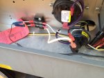
I tried removing the white wire coming from the switch and jumped it over on the block (as shown in the first picture), and the blower fired up and then the heater came on.

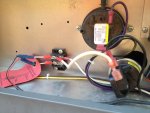
I then removed the wire and put it back to the normal position on the block (as shown in the second picture), and everything shut down.

Anyone have any ideas what's up? Any feedback would be greatly appreciated!

Thanks.
 

Attachments

  • heater1.jpg
    heater1.jpg
    341.3 KB · Views: 68
  • heater2.jpg
    heater2.jpg
    338.5 KB · Views: 64
It shouldn't matter which wire goes to which pressure switch connection. It's just a basic on-off switch that doesn't care which way electricity flows through it.

Your troubleshooting of moving the white wire to the top of the terminal block, and then having things function, points to the problem being in the circuit connected to the left side of the terminal block; the red and black wires that are crimped to the white wire stubs. Do the red and black wires go to a timer or after-run contacts attached to a timer? I think that's the source of your problem.
 
When I blew up your photo's it was obvious the installer (apologies if it was you) came from the school of making crimp connections with whatever hammer/chisel/vise-grips/pliers was closest at hand. If it was my heater, I'd cut the red and black wires off where they enter the blue splices and re-terminate those wires direct to the left side of the terminal block with properly crimped fork tongue terminals. There's no need to have those little white stub wires and the extra crimps in the electrical path.
 
You obviously have a control system which is the black and red wires on the other side of the terminal block. To eliminate the control system from the equation, you can remove those two wires and then connect those two terminals with a wire. Now see if the system works.

Also, how clean is your filter? Even though you see water coming out of the copper tube where the pressure switch is connected, it might not me enough pressure to activate the switch.
 
ps0303 said:
You obviously have a control system which is the black and red wires on the other side of the terminal block. To eliminate the control system from the equation, you can remove those two wires and then connect those two terminals with a wire. Now see if the system works.

Also, how clean is your filter? Even though you see water coming out of the copper tube where the pressure switch is connected, it might not me enough pressure to activate the switch.


He already performed the test you're suggesting and also proved that he had enough pressure, when he moved the white wire to the top left as shown in the first photo. That's when the heater fired up properly, proving the pressure switch was sensing pressure and completing the safety circuit.

The problem is with whatever the red and black wires are connected to (or the suspect crimp connections to the red and black wires).
 
Thread Status
Hello , This thread has been inactive for over 60 days. New postings here are unlikely to be seen or responded to by other members. For better visibility, consider Starting A New Thread.