
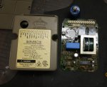
I haven't got time to check everything but I am hoping for a quick tip or a common thing to check first while waiting for the weekend. I had problem with the module (RAM-3MC7-04) before and it turned out the legs on the actual ignitor (not sure what's called but it generates the voltage to spark, under the red rubber boot in the pic) were loose and resoldeing fixed the problem. I wonder there is a procedure to test this part and change as needed instead of buying a new whole board (it it turns out the problem is within the board). So far I have continuity between 2 of the 3 legs and don't know if this is normal. I know I will have to test to make sure if the board gets proper power to it first but just hope for a quick tip before I get to it.
thx for any info[attachment=0:rlyiivzh]DSC04720rs[1].jpg[/attachment:rlyiivzh]
thx for any info[attachment=0:rlyiivzh]DSC04720rs[1].jpg[/attachment:rlyiivzh]
![DSC04720rs[1].jpg](/data/attachments/24/24054-3ba17b6031f2e8205c4ec32c74513f64.jpg)
![DSC04727rs[1].jpg](/data/attachments/24/24070-0706788c302a616a795751c074f39161.jpg)