Good morning. I am replacing my old Triton Purex pump with a Pentair Whisperflo 2 speed pump. I ran new wiring from timer to pump (black/red/green) due to age of old wiring and fraying. After hooking to switch inside motor housing (green to ground, black to black (center of switch), red to either yellow or white from switch (outer wires on switch), I get motor working when toggled one way, trips the breaker when toggled the other way. I reversed black and red with same results (as expected). I've looked at side wiring diagram and read various forums to no avail. Any help/direction would be greatly appreciated.

Pentair Whisperflo 2 speed pump tripping breaker
- Thread starter MikeL591
- Start date
You are using an out of date browser. It may not display this or other websites correctly.
You should upgrade or use an alternative browser.
You should upgrade or use an alternative browser.
I'm no electrical expert, but it could it be due to the size of the breaker? Is it tripping in the high speed position? Breakers get old and go bad too.
I thought I had seen a wiring diagram from the pump on a previous post here, so I checked again to find it. I found another post with the diagrams ("Wire help for a 2 speed Pentair SuperFlo" wire-help-for-a-2-speed-pentair-superflo-t61513.html) which is the same diagram for my Whisperflo. However, in wiring up as indicated in this post, I trip the breaker when I toggle to high. I pulled new 10 gauge stranded wire instead of the previous solid wire. I am not sure if that makes a difference. Also, where as the low side (black wire of switch) is connected via a wire nut, the high side to common is connected via the terminal block. Is it possible this connection is not solid and causing the problem? Again, thanks for the help.
Durk
0
Kinda hard to understand with all the colors. I just did my own WhisperFlo 2-speed and I can tell you this: the only wire from outside that goes to the switch is one hot lead to the center of the switch. The other hot lead goes to Terminal 1. The yellow and white from the switch should go to 2 and 3. Check this thread out:
http://www.troublefreepool.com/wiring-for-new-whisperflo-dual-speed-motor-t58010.html
When you do it right, you will have 230 V between terminals 1 and 2 with the switch in one position and 1 and 3 with the switch in the other position.
http://www.troublefreepool.com/wiring-for-new-whisperflo-dual-speed-motor-t58010.html
When you do it right, you will have 230 V between terminals 1 and 2 with the switch in one position and 1 and 3 with the switch in the other position.
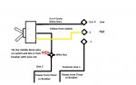
Here is a quick diagram I used to wire my 2-speed pump this week. You should not have anything connected to 2 (High) or 3/4 (Low) if you are using the switch on the pump. The only connections will be to post 1 on the pump terminal and then cut off the wire nut on the black middle wire of the switch, and connect this to your line 2 power. (See Diagram)
Okay, I like this diagram. Looking at the wiring block inside the pump housing, there is no visible wire (certainly no wire from the switch) on post 1. So this is where I should wire the other power wire? I will give this a shot (the only combination I did not try). Thanks!
Thread Status
Hello , This thread has been inactive for over 60 days. New postings here are unlikely to be seen or responded to by other members. For better visibility, consider Starting A New Thread.