10/2 or 10/3

Aug 10, 2013
30
Nashville, TN
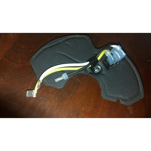
I am installing a new pump and have to run new wire for it. The pump is a two speed 230v motor.

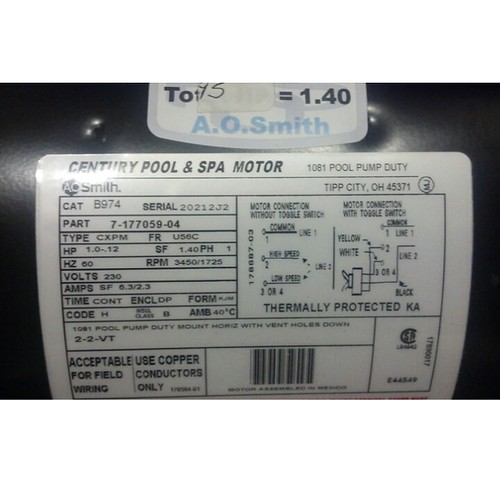
According to the diagram I only hook up two wires. One is the black which goes to the switch,and the other is the common, which connects to the common terminal. What do I do with the third wire, knowing that the bare wire connects to ground.

I read through a lot of the previous topics and remember one topic where it said to just cap the white wire. If this is actually true, can I just run 10/2. If that is correct then how do I wire it to the circuit?

I will post pics in a bit. I only have internet on my phone so it takes a bit to figure it all out.
 
The neutral isn't required for 220V motors. When running through conduit, it's much easier to pull individual strands than cable.
 
It really depends on where you are putting your speed control. If your speed control is out by the pump, then all you need is the 10/2 out to your switchgear (and 10/3 fom the switch to the motor). If your switch is a long distance from the motor - then you need the 10/3.

Bottomline - you need the 10/3 from your speed selection switch to your motor.

If you are getting one of those motors that have the builtin timer / speed switch - then you can probably get by with just the 10/2 .

When using the 10/3 from the switch to the pump, it should be wired this way -
1 red wire - high speed
1 black wire - low speed (these two can be switched with no lose of functionality)
1 white wire - common
1 green wire - ground.
 
9627498077_a9f503c6b9.jpg


9630717262_3e4a61262f.jpg


9627485601_3abc87d8be.jpg
 
So I could use 10/2 and connect
ground to buss bar
White to breaker (wrapped in red electrical tape)
Black to other spot in breaker.


Then on pump...
Ground to ground screw
White (with red tape) to common
Black to black on switch.
Yellow and white to hi and low connectors
 
You only need 3 wires (line1, line2, ground) run to the motor if you are using that switch.

The diagram is straightforward. One Line to Terminal 1. The other Line to the black wire on the switch. Then the switch white to terminal 3/4 and the switch yellow to terminal 2. And the ground to the green screw or course. And a bonding wire to the outside terminal.

EDIT to correct that it is 230V and not 120V.
 
You need two hot wires and a ground (and your bonding conductor, of course).

You hook one hot wire to terminal 1 (common), and the other one to the capped off black wire going to the switch and ground to ground. You also plug the yellow wire from the switch onto terminal #2 (high Speed) and the white wire from the switch to terminal #3or4 (low speed).
 
If you are worried about code compliance, it is against the NEC code to change the color of wires with tape if they are smaller (higher number) than about 4 or 6 AWG (I forget which, might even be bigger than that). Basically this means the only wires that it is code legal to change color using marking tape are those larger sizes that are typically only available in black. Also as has already been mentioned it is a code violation to run UF or NM (romex) inside a conduit, you can typically only code legally run individual wires inside conduit (there are a few rare exceptions here).
 

Enjoying this content?

Support TFP with a donation.

Give Support
Thread Status
Hello , This thread has been inactive for over 60 days. New postings here are unlikely to be seen or responded to by other members. For better visibility, consider Starting A New Thread.