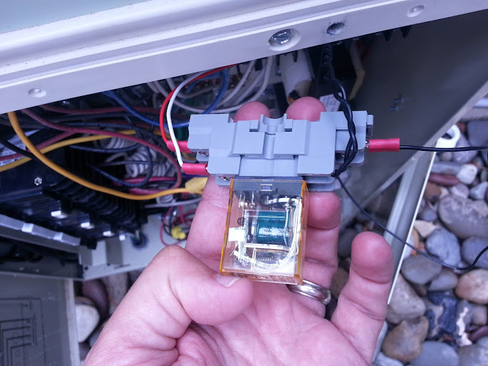
Adding 3rd Valve/Actuator to my EasyTouch 8 System

jhav

0
LifeTime Supporter
Jun 29, 2011
53
Control third valve with Easytouch 8

OK - I spent most of today trying to get my actuator working... I think I'm close, but it is not quite there. I thought that I had followed the wiring diagrams from the previously linked thread perfectly, but here is my result:

When I hit the 'Aux 7' button on my EasyTouch, the actuator turns to its correct set point... however, when I hit the 'Aux 7' button a second time, the actuator fails to turn again (back to its original spot). Additionally, while the 'Aux 7' button is lit on my panel, I am able to manually toggle the actuator to force it to turn in either direction... however, when the Aux 7 button is turned off, there is no response from the actuator.

It appears as if the 'Aux 7' button is merely providing power to the actuator when it is lit (and causing it to rotate in one direction) --- however, when Aux 7 is turned off, it appears to be cutting power to the actuator entirely.

From what I've read, I believe that the BLACK wire for the Pentair/Compool actuator is common with the red and white wires being switched... but I am not 100% on this.

The behavior I am hoping to achieve is that when Aux 7 is turned on, it will rotate the actuator in one direction --- when Aux 7 is turned off, it will rotate the actuator in the opposite direction. Any input/insight would be enormously appreciated!
 
Re: I have a need for a third valve for my system

Actuators work off of a three wire connection. One wire is common, one is turn one way, and the last is turn the other way.

From your description you are not supplying power to the "other way" wire when the relay is off. A SPDT relay is the right kind of relay, so it is capable of doing what you want. You either missed installing a wire, or have a bad connection somewhere.
 
Re: I have a need for a third valve for my system

Thanks Jason - I played with it for way too long today and couldn't get it to work... what you said makes total sense -- I'll test it out again tomorrow.

Right now I have the 'red' 24V wire from the EZ touch breaker spliced into the black wire of the actuator. I have the red/white wire from the EZ touch breaker spliced into the SPDT. I have the red and white wires from the actuator connected to the SPDT along with the 2 black relay wires.

Just to clarify, I removed the two back relay wires from their original connection in the high-voltage area of the EZ touch and connected them directly to the SPDT --- there should not be any connections of wires in the high-voltage area of the box (except those coming from the low-voltage area to the SPDT... correct?

Also, from a configuration standpoint, I should be setting up the EZ Touch to control this relay under Aux 7 -- not as a feature.. right?
 
I haven't seen that particular arraignment of connections on a relay. It seems possible that you have the "center" terminal on the relay mis-identified. A little playing around with a multi-meter should allow you to confirm which terminal is the "center" one.
 
Finally got it correct --- here is the correct wiring for the IDEC SPDT that I purchased in case others follow a similar path:

Top section ---
1) RED wire is spliced and connected to BLACK wire from Actuator - NOTE: for The Pentair/Compool CVA24 Actuator, the BLACK wire is COMMON; the RED & WHITE wires are switched.
2) RED/WHITE wire is spliced - and connected to the SPDT Relay (I used a black in my splice)
IMG_20130630_114250.jpg


Bottom Section -
1) I removed the two black wires from an open relay (I used Relay #7) from their regular connection and reconnected them to screws 13 & 14 of the SPDT Relay (you'll need to cut of the existing spade connectors from the relay wires as they are to large for the IDEC Relay - I simply stripped off the ends and ran them under the screws)

2) The spliced wire from the RED/WHITE connection in Step 2 above (mine is black) Is connected to Screw #9.

3) The RED & WHITE wires from the Actuator are connected to screws #1 & #5 -- It shouldn't matter which is connected where.

NOTE - I purchased a bag of cheap crimped spade connectors from Radio Shack for the wires connected to screws #1, #5, & #9 - This is not necessary as you could certainly just run bare wire under the screws.

4) I got some double-sided velcro tape to stick the SPDT relay into an open area in the High-Voltage area of the EasyTouch (I have space right above what was 'relay #7).

5) That's it.... the actuator will now turn one way when Aux 7 is activated, and turn the opposite direction when it is deactivated.

IMG_20130701_102714.jpg
 
  • Like
Reactions: GDN
I found this post and I am trying to accomplish the same thing on the same system. however when I pulled up the relay it says it is a 24vdc relay. How does this work on a 24vac system. also why can I not just wire the 2 actuators together. no more than 3 on the circuit would be running at a single time?
 
jmcdtx said:
I found this post and I am trying to accomplish the same thing on the same system. however when I pulled up the relay it says it is a 24vdc relay. How does this work on a 24vac system. also why can I not just wire the 2 actuators together. no more than 3 on the circuit would be running at a single time?

The actuators in the EasyTouch system are DC --- not AC -- so, you need a 24vdc spdt for the EasyTouch relay.

I'm not clear on your setup, but wiring 2 actuators together would not have helped me at all -- I need to control each of my 3 actuators independently - having them operate together would not benefit my setup.
 

Enjoying this content?

Support TFP with a donation.

Give Support
The motors in the CVA24 actuators are actually two AC synchronous motors, stacked one on top of the other one for each direction. The big mylar capacitor in the actuator is for phase shifting to get the activated motor started, depending on which of the two wires (white and black) has the 24 VAC applied in reference to the common (black) wire. Applying DC voltage to this type of motor would not cause it to turn whatsoever and may even overheat it.
 
Guys... I think what we have here is the typical "Failure to Communicate"... :cool:

I suspect it is just a nomenclature issue. Just to make sure everyone is on the same page...

The EasyTouch relay coils require 24 VDC to turn the relay on/off. The voltage passing through the relay contacts and going to the valve actuators is 24 VAC.

Jim R.
 
Just wanted to report that although this thread is older the info still works with my just purchased Easytouch 8 panel.
I just ordered the below items (searched for them or follow link in post #1 above). Then I just followed the instructions from post#8 above and worked as expected. It was all of $20 shipped for the parts and pretty easy to setup using the instructions. It does help to have experience wiring low voltage circuits and relays, but I think most can tackle this if you are somewhat handy. Sure beats buying the Jandy board for ~$120.
IDEC Corporation SH1B-05 - Socket
IDEC Corporation RH1B-ULDC24V - SPDT relay that fits above socket


Moderators - it might be a good idea to make this a sticky.
 
Actually if you add this, it will add the valves and dovetail into your EasyTouch, IntelliTouch, or IntelliCenter system. That means you can add a valve but it still works with ScreenLogic when the circuit is activated. You can add as many valves as you like and as many circuits as you like.
 

Enjoying this content?

Support TFP with a donation.

Give Support
Thread Status
Hello , This thread has been inactive for over 60 days. New postings here are unlikely to be seen or responded to by other members. For better visibility, consider Starting A New Thread.