Wiring advice needed for INtelliflo Setup and existing timer

Apr 14, 2013
78
Hi there,

I have the following setup today (I am in Canada) and would like some advice on proper wiring of my new setup

Current setup:
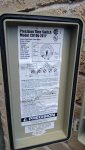
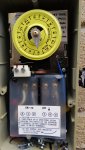
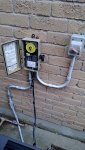
20 AMP 240 Volt breaker - one line to pool pad
- intermatic timer with fireman switch hookup
- Raypak digital heater hooked into timer as L2
- old single speed pump wired into timer as L1
- emergency shut off switch that overrides timer

New Setup:
-intelliflo pump to replace old pump
- Intellichlor chlorinator

My challenge is that i'm reading that I should not keep the pump timer and should feed the Intelliflo directly. Is this true?

To keep this simple, I was thinking of keeping the timer and removing the pins (so it never shuts off). That way I wouldn't have to rewire the heater which looked a bit complex. I was also thinking of wiring the Chlorinator to the L2 terminal to share the L2 with the Raypak. My emergency shut off could then shut everything off.

OR, should I pull a new wire for the pump and leave the timer to control the heater and chlorinator?

Any suggestions would be greatly appreciated (would like to ensure I comply with Canadian codes).
 
Re: Wiring advice needed for INtelliflo Setup and existing t

Welcome to TFP!

There is nothing wrong with switching an IntelliFlo pump on/off with an external timer as long as you are ready to accept that it will only run at one speed (which can be any speed you pick). To put that another way, you can't use the IntelliFlo's internal timer at all if you are controlling the pump from an external timer.

Another option, more complex/expensive, is to get a current switched relay that will power up the heater and SWG when it detects the IntelliFlo drawing more power than it does when off (put powered up).

In any case keeping the pump run time and the heater/SWG coordinated is a good secondary safety precaution. There are other ways to do it, but these two are some of the least expensive and easiest to setup.
 
Re: Wiring advice needed for INtelliflo Setup and existing t

Interesting - if I leave the timer on 100% of the time and use the Intelliflo timer - will that not work to control the pump speeds etc? I'm basically leaving the mechanical timer in place as a convenience of not having to rewire the heater, SWG etc. I figured so long as the mechanical timer never went off, the Intelliflo internal timer would do most of the pump control.

I realize i'm giving up the fireman switch as the intelliflo timer will have no way of shutting the heater down - but I plan on running this pump 24x7.
 
Re: Wiring advice needed for INtelliflo Setup and existing t

Yes, that will all work. Using the internal timer you can change speeds on a preset pattern and everything will work. However, if you decide not to run the IntelliFlo 24/7 there is a safety issue with the SWG being powered up when the pump is off.

However, unless you have a really huge pool, it is quite unlikely that you really want the pump running 24/7. At it's more energy efficient speed, around 1000 RPM, the IntelliFlo moves 20+ GPM in most pools, which leads to 8-15 hour run times for an average pool.
 
Re: Wiring advice needed for INtelliflo Setup and existing t

I guess another way to do this would be to run a dedicated line for the pump and leave the timer in place for heater + SWG control?

Or run a thick line out to the pad and put an outdoor subpanel with a few breakers in it, GFCI and feed the pump, SWG and heater all separately?
 
Re: Wiring advice needed for INtelliflo Setup and existing t

Your first idea will work, but the second one, while nice to have, won't affect anything we have been discussing so far.

Yet another option is to get a simple automation system, like a SunTouch. Though if you don't have anything else going on (like a spa) then there isn't much point.
 
Re: Wiring advice needed for INtelliflo Setup and existing t

Move the power wires from the pump from the load side to the line side so that it always has power and the timer still controls chlorinator and heater. In other words, wire the pump in with the incoming power to the timer.
 
Re: Wiring advice needed for INtelliflo Setup and existing t

ok that makes sense.. So put a junction before the timer and splice off to the pump and then splice to the timer?

Still ok to use the same 15 Amp 240v line for all these components? I was going to be put a siemen GFCI breaker in the panel as it doesn't have one now (original wiring was done 15 + years ago).
 
Re: Wiring advice needed for INtelliflo Setup and existing t

Depending on what timer you have, there may not have to be any splicing done. A picture or model number of timer would help.

I put that breaker on all of my intelliflo/pro installs
 
Re: Wiring advice needed for INtelliflo Setup and existing t

Hi there - I have attached some pics of the setup and timer. The timer is a Precision timer. Do you think I can add Chlorinator and Heater to Load 2 and leave Intelliflo on Load 1?

If so, then I can control everything with existing shut off switch on the right. Let me know what you guys think. If I need to rewire I will..
 

Attachments

  • WP_20130415_003.jpg
    WP_20130415_003.jpg
    384.6 KB · Views: 127
  • WP_20130415_004.jpg
    WP_20130415_004.jpg
    411.5 KB · Views: 128
  • WP_20130415_005.jpg
    WP_20130415_005.jpg
    479 KB · Views: 128

Enjoying this content?

Support TFP with a donation.

Give Support
Re: Wiring advice needed for INtelliflo Setup and existing t

I just read on Pentair install manual that the pump needs a 20 amp breaker. Right now I have 15 amp breaker (old whisperflo only pulled 8 amps). So this likely means new wiring out to the pad.. Maybe a 30 amp circuit with GFCI breaker and appropriate wiring. Not sure if my timer can handle this?
 
Re: Wiring advice needed for INtelliflo Setup and existing t

What I was suggesting was to move the power wires to the pump over to line 1 and line 2. That way it will always have power.

You certainly want the 20 amp GFCI breaker on the pump circuit. I've seen them consistently trip weaker, lower rated breakers. Looks like the timer is rated for 40 amps so a 30 amp shouldn't be an issue. Is there a subpanel at the equipment or does power come from main panel into your timer box?

edit: I just read that you have no subpanel outside. Replace the 15 amp breaker with the 20 amp GFCI and call it a day.
 
Re: Wiring advice needed for INtelliflo Setup and existing t

Power comes from main panel in the basement. Only a 30 ft run of wire to get to the pad from basement panel. So not a big deal to pull a new thicker gauge wire capable of 30 amps out to the timer.

Not sure I understand what you mean be moving the power wires to pump over to line 1 and line 2?

Where should I wire the chlorinator?
 
Re: Wiring advice needed for INtelliflo Setup and existing t

ok so replace the 15 amp with 20 amp GFCI breaker at the main panel. Run that wire to the existing timer and from there wire pump, chlorinator, and heater off timer? Will 20 amps suffice for all 3 or should I really be at 30 amps?
 
Re: Wiring advice needed for INtelliflo Setup and existing t

Yeah I'd just install the 20 amp at the panel and run everything basically like you have it now, other than the new pump getting constant power from line 1 and 2.

Technically the manual calls for a dedicated 20 amp gfci breaker for that pump. If you don't have a subpanel and its not in the plans to install one you may as well try it out with the smaller one first. Salt systems and gas heaters don't have much power draw, so you should be fine.
 
Re: Wiring advice needed for INtelliflo Setup and existing t

So got everything ready to go. Pool store guy insisted I 'bond' the heater pump and SWG together. How do I bond properly? Pool is very old so no bonding wire /points anywhere. Should I just run the bonding wire between the three pieces of equip and call it a day or does it need to go into the earth. I am told no,ding is very different then grounding (everything to be grounded back to panel via ground wire).
 
Re: Wiring advice needed for INtelliflo Setup and existing t

For bonding you want to use #8 bare copper wire to connect the pump, SWG, heater, and everything metal that is within one meter of the water horizontally. If your pool is fiberglass or vinyl lined you should also get a special piece of pipe designed to bond the water, which also gets connected with #8 copper to everything else. Also, the copper should run in a loop all the way around the pool, and if there is rebar in the deck and/or pool shell it should connect to that in four different places spread around the pool.

No grounding rod is used, nor is the bonding connected to grounding except perhaps through the chassis of the pump and heater.

Ideally you should do all of that, but it is worth investigating to see if any of it was done at any point in the past, which you might be able to reuse.
 
Re: Wiring advice needed for INtelliflo Setup and existing t

Pool is really old so there is no sign of bonding. I am going to loop together swg, heater and motor. If I ever end up redoing the concrete decking I will redo that part properly. I assume bonding the three pieces if equip is better than not doing it all?
 
Re: Wiring advice needed for INtelliflo Setup and existing t

tommytuna said:
I assume bonding the three pieces if equip is better than not doing it all?
Sure, better than nothing, but not much better.

I'm not trying to be harsh, that is just the way it is. It's your pool you can do what you want.

If you can connect to any rebar anywhere in the deck that is way better than nothing.
 
Thread Status
Hello , This thread has been inactive for over 60 days. New postings here are unlikely to be seen or responded to by other members. For better visibility, consider Starting A New Thread.