Intermatic timer for 2-speed pump

Melt In The Sun

0
TFP Expert
LifeTime Supporter
Oct 29, 2009
3,894
Tucson, AZ
I bought the 2-speed Tristar in my signature several months ago, and now I'm thinking maybe I'll actually install it. The old Super II has started to leak a steady trickle instead of just a constant drip.

I have a T10004 enclosure and I believe that I just need to get a T106M to put in the same enclosure. I know I could just manually change the speeds with a DPDT switch, but I'd like to automate it.

Can someone confirm that the T106M is what I need?

DSCN7290.jpg
 
Seems like there are a lot of questions about timers the last few days.

I would agree that you would need the T106M to select the speed. Note you will need to move the power wires for the T106 clock over to the T104 Line power supply since the T106 line power will switch on and off due to the T104 timer.

EDIT: Of course I just assumed that your pump is 240V ... if it is not, then I have not looked up the wiring for a 120V 2-speed yet.
 
Quick wiring question!

I believe I have the timers all wired correctly. The on/off timer is on the right, and the low/high on the left. Both clock motors are wired to the line so they both will turn all the time, rather than the low/high timer only turning when the pump runs. Line and neutral to the low/high timer are controlled by the on/off timer. So, I think I have it set up so that the wires headed to the pump are neutral (white), high speed line (red), low speed line (black), and ground. My question is with the wiring diagram for the pump...it shows "common" and "line 2" on the same terminal, which doesn't make sense to me :scratch: 
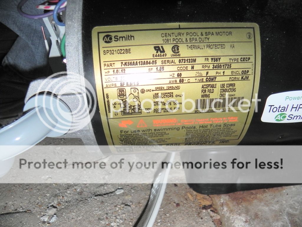
On the wiring diagram for the timers, it shows neutral being connected to "A" which on the pump diagram is "LO"
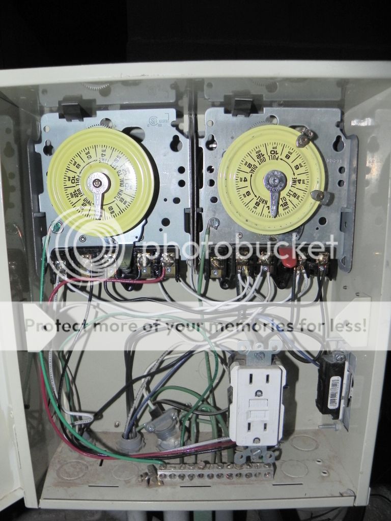
Can someone tell me which wires go to which terminals? My gut says white to COM/L2, black to LO/A, and red to HI/L1. I'm not comfortable though...can someone confirm or correct this please?

DSCN7402.jpg

DSCN7403.jpg

DSCN7406.jpg

DSCN7410.jpg
 
I can not confirm off the top of my head, or maybe I am just repeating what you said.

I thought you said the motor was 240v right? Then there it's no neutral. To the pump there should just be a ground. Line 1 off one leg from the on/off timer to the motor ... guess you called this the common and that would go to L2. And then 2 power lines from the speed timer (fed off line 2 from the on/off timer) that attach to the 2 speed terminals in the motor. So there should be 4 wires from the timers to the motor. None of those should really be white to avoid confusion in the future, since it will be hot ... or at least wrap black tape on the ends.

I think there would be 4 wires for 120 volt as well, the 2 speed wires for the hot, the neutral, and the ground.

Edit: you wired the 106 to the single pole double throw directions right? There is no neutral in that case. And you have to add a jumper.

Edit 2: where is the white wire fed from? Looks like from the power terminal on the 106 ? I would feed it directly off the switched side on the 104 from the leg that is not run to the 106, so you are sure they are on opposite phases.

Posted from my Droid with Tapatalk ... sorry if my response is short ;)
 
Yes, 220, no neutral. I blame that on the sleep deprivation...new baby and all. You believe that, right? :-D

There is a jumper in place and the white is hooked up correctly, if in a roundabout way. At first I had the clock timer wired as the diagram shows, so I needed the white over there. I can do like you suggested, or not, it's the same.

I get it now...thanks for your help!
 
Thread Status
Hello , This thread has been inactive for over 60 days. New postings here are unlikely to be seen or responded to by other members. For better visibility, consider Starting A New Thread.