
I have been lurking here for a while and have adopted the BBB method and it has worked quite well, and saved me a ton of money and headaches. I even turned my dad on to it. So, since you have all saved me a lot of money, I figured I'd return the favor.
I was re-plumbing my filter the other day (it was sitting at a 15 deg angle from the previous owner) and after hooking things up, I was getting a "no flow" indicator on the control panel. I thought "hmm, this little switch can't cost too much to replace." Much to my surprise, this little piece cost upwards of $100! D*mn if I'm going to pay that much. Here's my "fix":
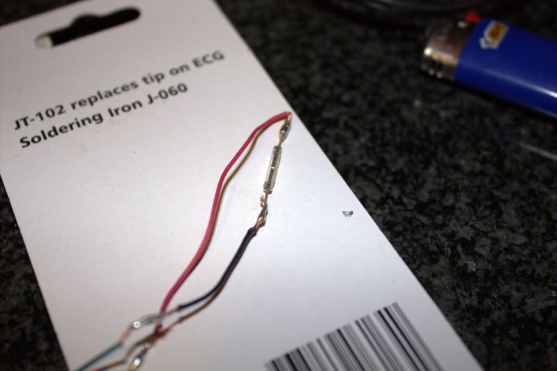
What you need - A magnetic reed switch like this one http://farm4.staticflickr.com/3500/3754406553_5d1131dcb2.jpg (I got mine for $4.80 at a local electronics supply store. Don't bother with RadioShack, they don't carry them) a soldering iron, silicone caulk, and about 30 minutes
Steps:
1 - Remove the switch and plug the hole.
2 - Take the wires and cut them. Strip them to expose the ends.
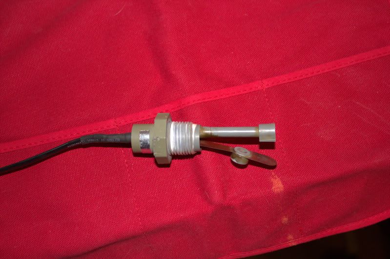
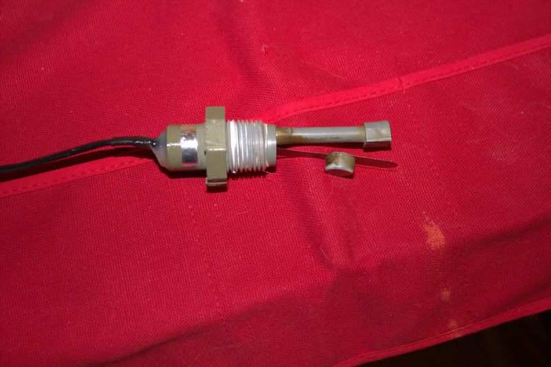
3 - Drill out the epoxy on the top side of the switch where the wires enter so it looks something like this.
(I drilled the bottom out too..but looking back, I would have been better off only drilling from the top. If you leave the bottom intact, there is less of a chance of water getting to the wires. Oh well, live and learn.)
4 - Solder the wires to either end of the reed switch so the wires are going one direction
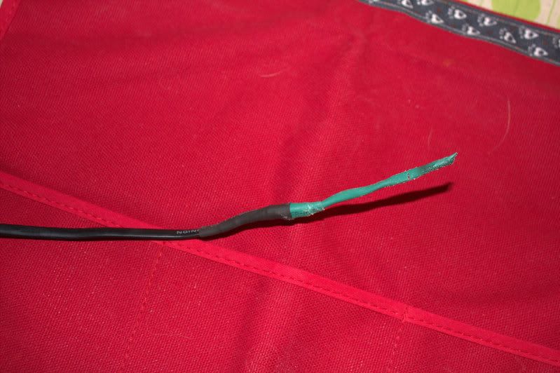
5 - Wrap and heat shrink the wires (I guess this is optional, but I'd recommend it)
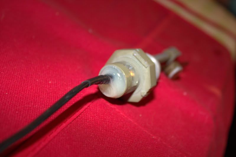
6 - Insert the wires into the drilled out switch assembly.
7 - Take it to the control panel, plug the jack in and hold the switch closed and verify that its making a connection (the no flow indicator should start blinking)
8 - If everything looks good, put some silicone into the openings you drilled out and insert the wires back into the assembly.
9 - Repeat step 7 before the silicone starts to set so you can move the wires in or out if needed. The switch needs to be even with the magnet on the flapper in order for the switch to activate.
10 - Let it set overnight.
I did this today, and everything is looking awesome! I took the opportunity to switch the wires to an old phone wire I had sitting around as my original wire was cracking and crumbly. Who knows how long this fix will last, but the price of the reed switch ($5) is well worth the experiment in my mind. And don't worry, the control panel is powered by the pump timer, so it only has power when the pump is running. So If something shorts creating a closed circuit, the SWG will only be on when water is moving anyway.
Don't be afraid to try this! you really have nothing to lose (well, maybe $5). Soldering is the hardest part. I'm not the most experienced, and my solders are crappy, as you can see, and they still work..
Thanks again for all the help and info guys! I hope this helps some people. If anyone has any questions, just ask!
I was re-plumbing my filter the other day (it was sitting at a 15 deg angle from the previous owner) and after hooking things up, I was getting a "no flow" indicator on the control panel. I thought "hmm, this little switch can't cost too much to replace." Much to my surprise, this little piece cost upwards of $100! D*mn if I'm going to pay that much. Here's my "fix":
What you need - A magnetic reed switch like this one http://farm4.staticflickr.com/3500/3754406553_5d1131dcb2.jpg (I got mine for $4.80 at a local electronics supply store. Don't bother with RadioShack, they don't carry them) a soldering iron, silicone caulk, and about 30 minutes
Steps:
1 - Remove the switch and plug the hole.
2 - Take the wires and cut them. Strip them to expose the ends.
3 - Drill out the epoxy on the top side of the switch where the wires enter so it looks something like this.
(I drilled the bottom out too..but looking back, I would have been better off only drilling from the top. If you leave the bottom intact, there is less of a chance of water getting to the wires. Oh well, live and learn.)
4 - Solder the wires to either end of the reed switch so the wires are going one direction
5 - Wrap and heat shrink the wires (I guess this is optional, but I'd recommend it)
6 - Insert the wires into the drilled out switch assembly.
7 - Take it to the control panel, plug the jack in and hold the switch closed and verify that its making a connection (the no flow indicator should start blinking)
8 - If everything looks good, put some silicone into the openings you drilled out and insert the wires back into the assembly.
9 - Repeat step 7 before the silicone starts to set so you can move the wires in or out if needed. The switch needs to be even with the magnet on the flapper in order for the switch to activate.
10 - Let it set overnight.
I did this today, and everything is looking awesome! I took the opportunity to switch the wires to an old phone wire I had sitting around as my original wire was cracking and crumbly. Who knows how long this fix will last, but the price of the reed switch ($5) is well worth the experiment in my mind. And don't worry, the control panel is powered by the pump timer, so it only has power when the pump is running. So If something shorts creating a closed circuit, the SWG will only be on when water is moving anyway.
Don't be afraid to try this! you really have nothing to lose (well, maybe $5). Soldering is the hardest part. I'm not the most experienced, and my solders are crappy, as you can see, and they still work..
Thanks again for all the help and info guys! I hope this helps some people. If anyone has any questions, just ask!
")