So yesterday morning after a night of storms my pump wasn't working. For some reason it does this on occasion, but usually I can trip the breaker and it'll start back up. Not yesterday. It did this one other time in the season and it cost me over $100 for the pool guy to come and fix it. Anything I can do myself to try and fix it. I already tried bypassing the timer, but no luck. Pool guy doesn't work on Mondays. I go to church with him, but he wasn't there yesterday. Need to get this thing back up and running. Any help would be appreciated!

pump not working
- Thread starter gcates
- Start date
You are using an out of date browser. It may not display this or other websites correctly.
You should upgrade or use an alternative browser.
You should upgrade or use an alternative browser.
Is your pump impellor moving freely? With power removed from the pump, see if it will rotate.
What did he do to "fix it" last time? ... for only $100 it was obviously something easy that did not require a lot of parts.
Not sure what he did last time. I'm sure it was on my invoice, but that was at the begining of the season and once my check cleared I tossed it. I'm back at work now, and will check the impellor when I get back home.
I went out to check the impellor and was hoping to find a fan like part to my pump to try and rotate. My pump has a solid casing around it and I'm not 100% sure what the impellor is. But there was nothing visible from the outside that I could try to rotate manually.
The impeller is inside the casing. You have to take it apart to see the impeller. However, you can sometimes reach a finger it through the pump basket and feel the impeller and even sometimes turn it. With the power OFF of course.
Trouble free comes through again!! After getting info here and some from youtube and remembering some other symptoms I'd been having, I decided my impeller was the problem. I wanted to open up the pump and clean it out good, but the previous owners had the seal between the pump and the basket caulked all to heaven. So I stuck my screwdriver in through the intake and moved the impeller some. It turned but not as freely as it should. Turned the breaker back on and my pump is running again. Now my problem is I can't figure how to rewire my timer. That was probably a snap judgment to unhook. Any help there? :lol: I'll try to post a diagram of my setup later. Thanks again!!
So without having taking a picture of my timer this is the setup. Two lines plus the ground wire coming from the house. Two lines and the ground going down to the pump. A ground and three lines coming from the timer. They are hooked up like this: NO COMMON CLOCK. There is an extra pole betwween the NO and the COMMON, then the clock. The ground wire is above and to the right. Any help on how those are to be rewired? Thanks again for all the help!!
It depends if it's a 115 volt or 230 volt timer, and if it's a single pole or double pole.
- Jun 14, 2012
- 2,668
- Pool Size
- 13500
- Surface
- Vinyl
- Chlorine
- Salt Water Generator
- SWG Type
- CircuPool Edge-40
Who makes the timer. If it's Intermatic (yellow dial) you can probably find the installation instructions here:
http://www.intermatic.com/en/ProductRes ... ation.aspx
http://www.intermatic.com/en/ProductRes ... ation.aspx
UnderWaterVanya said:Who makes the timer. If it's Intermatic (yellow dial) you can probably find the installation instructions here:
http://www.intermatic.com/en/ProductRes ... ation.aspx
It is an Intermatic Model T-1906. Thanks for the link, I'll check it out.
Okay, so this is the exact diagram on the inside of the door of the timer....I'm just not smart enough to figure it out. :lol:
http://www.intermatic.com/~/media/Inter ... tions.ashx
I hope the link also answers the question about the voltage.
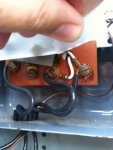
Again there are two wires and the ground that come from the house, and two wires plus the ground that go to the pump. And the timer is wired like this: The three electrical wires come from the first N.O. position, the third Com., and the clock. The ground is above and to the right. Here is a picture I was able to upload.
http://www.intermatic.com/~/media/Inter ... tions.ashx
I hope the link also answers the question about the voltage.
Again there are two wires and the ground that come from the house, and two wires plus the ground that go to the pump. And the timer is wired like this: The three electrical wires come from the first N.O. position, the third Com., and the clock. The ground is above and to the right. Here is a picture I was able to upload.
Attachments
- Jun 14, 2012
- 2,668
- Pool Size
- 13500
- Surface
- Vinyl
- Chlorine
- Salt Water Generator
- SWG Type
- CircuPool Edge-40
gcates said:Again there are two wires and the ground that come from the house, and two wires plus the ground that go to the pump. And the timer is wired like this: The three electrical wires come from the first N.O. position, the third Com., and the clock. The ground is above and to the right. Here is a picture I was able to upload.
Which wires in the picture go with what?
UnderWaterVanya said:gcates said:Again there are two wires and the ground that come from the house, and two wires plus the ground that go to the pump. And the timer is wired like this: The three electrical wires come from the first N.O. position, the third Com., and the clock. The ground is above and to the right. Here is a picture I was able to upload.
Which wires in the picture go with what?
That's what I'm not sure of. I disconnected the power to bypass the timer. Now I've got those three wires connected to the timer that run down into the housing but aren't connected. I know the power from the house went to the timer and back down to the pump, I'm just not sure of which were wired together.
- Jun 14, 2012
- 2,668
- Pool Size
- 13500
- Surface
- Vinyl
- Chlorine
- Salt Water Generator
- SWG Type
- CircuPool Edge-40
gcates said:UnderWaterVanya said:gcates said:Again there are two wires and the ground that come from the house, and two wires plus the ground that go to the pump. And the timer is wired like this: The three electrical wires come from the first N.O. position, the third Com., and the clock. The ground is above and to the right. Here is a picture I was able to upload.
Which wires in the picture go with what?
That's what I'm not sure of. I disconnected the power to bypass the timer. Now I've got those three wires connected to the timer that run down into the housing but aren't connected. I know the power from the house went to the timer and back down to the pump, I'm just not sure of which were wired together.
Let me phrase this differently...
Are the wires you are showing all of the wires or just some of them - for example is the household source wire not yet shown? Are they still where they were when you first opened the timer or randomly connected? Which device do the black wires go to? Which device do the white wires go to?
[/quote]
Let me phrase this differently...
Are the wires you are showing all of the wires or just some of them - for example is the household source wire not yet shown? Are they still where they were when you first opened the timer or randomly connected? Which device do the black wires go to? Which device do the white wires go to?[/quote]
The wires showing are of the wires that are connected to the timer and go out into the housing. They aren't connected to anything on the other end. The source wires aren't shown, but are still there and currently connected directly to the pump. The white wires are connected to the timer on both ends...I haven't messed with those. My only question is about the black wires connected to the timer and run out and not connected on the other end.
There should be wires from the supply to the timer and wires from the timer to the pump .... 4 wires in total (ignoring the ground).
I think more pictures are required because based on that picture I have no idea what is going on.
Here are better diagrams:
http://waterheatertimer.org/How-to-wire ... timer.html
I think you want the 240V water heater timer circuit.
I think more pictures are required because based on that picture I have no idea what is going on.
Here are better diagrams:
http://waterheatertimer.org/How-to-wire ... timer.html
I think you want the 240V water heater timer circuit.
That's a 230 volt timer.
The two white wires are the clock leads.
I'm having to guess a little here so if something doesn't match what you see let us know and we'll rethink it.
My guess is that they had the power from the house and the power to the pump wire-nutted to the landed pigtails in the bottom of the timer.
If you can take a pic showing a little more of the timer I may be better able to confirm.
At any rate below is how it hooks up.
All the grounds hook together under the same terminal strip.
The power from the house goes to the "Com" & "Clock" terminals. It doesn't matter which wire goes on which terminal.
The power to the pump hooks to the "N.O." & "Clock" terminals. It doesn't matter which wire goes on which terminal.
jblizzle said:There should be wires from the supply to the timer and wires from the timer to the pump .... 4 wires in total (ignoring the ground).
Theres my problem. There are two wires from supply and two wires to the pump, but as you can see in the picture only three wires to connect on the timer.
I think more pictures are required because based on that picture I have no idea what is going on.
You're probably right. I rushed out this morning to get that one, and it obviously doesn't tell the whole story. I'll try to do better when I get home from work.
Here are better diagrams:
http://waterheatertimer.org/How-to-wire ... timer.html
I think you want the 240V water heater timer circuit.
Those diagrams are better, and I think you're right about the 240V water heater circuit. It makes the most sense, but it seems I've lost a wire! :lol:
Bama Rambler said:That's a 130 volt timer.
The two white wires are the clock leads.
I'm having to guess a little here so if something doesn't match what you see let us know and we'll rethink it.
My guess is that they had the power from the house and the power to the pump wire-nutted to the landed pigtails in the bottom of the timer.
If you can take a pic showing a little more of the timer I may be better able to confirm.
At any rate below is how it hooks up.
All the grounds hook together under the same terminal strip.
The power from the house goes to the "Com" & "Clock" terminals. It doesn't matter which wire goes on which terminal.
The power to the pump hooks to the "N.O." & "Clock" terminals. It doesn't matter which wire goes on which terminal.
I know for sure that the first bolded sentence is right. I remember that from unhooking. I think the other stuff is right too, but there doesn't seem to be that fourth wire coming from the clock to the pump.
Thread Status
Hello , This thread has been inactive for over 60 days. New postings here are unlikely to be seen or responded to by other members. For better visibility, consider Starting A New Thread.