DIY with Liquid Chlorine, ORP Probe, Arduino

Status
Not open for further replies.
G

Guest

This is for informational purposes only. I've ran into some things that I'm sure other people would be interested to know, hence this post. I will link to sites, and these products work for me, but I do not endorse them in any way. I am posting this in the ORP forum since this is the most interesting part of my setup.

My automation system has been in progress for a few years, and this is the latest revision. It has:
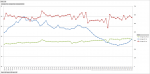
-Supply, Return Temps (10k thermistors)
-Pump current Sensor
-Filter pressure sensor
-ORP probe
-Control of pump high/low, chlorine feeder, and heater.

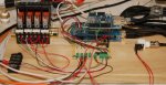
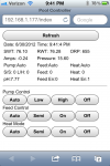
It is designed around an Arduino Mega 2560 with the Ethernet shield. I have the prototype shield on that to break out I/O to an external board to interface with relays and such. (see picture)

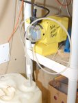
I bought a LMI Milton Roy diaphragm pump off ebay. I bought the multipurpose valve from a LMI dealer that sits on top which makes it a breeze to prime and test. I buy 5 gallon 12.5% chlorine from a local pool shop, and use that is a dispenser. I drilled some holes in a lid to put a dip tube and return line into. The dip tube is a toilet water line with the end cut off. (see picture)

Outside, I put a ¼” adapter into spare port on my multiport valve to feed into. I struggled to find cheap fittings for this setup as the local big boxes don’t have enough selection. I use a lot of Parker Fast-Tite fittings. They are cheap and readily available at Grainger.

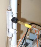
My ORP probe is from atlas scientific. They make a handy board to deal with reading the millivolt readings and hand off with simple serial commands. I intend on buying the pH probe shortly. I found a fitting (Aquatic Life ½” compression probe fitting) that I used to put the probe into my test manifold. The manifold is just made of PVC parts I got at Menards. The manifold is connected to the drain port on my pump (with a ¼” fitting) and returns into a pipe down stream from the filter. It has a decent flow, but not too much.

If anyone wants to talk programming, electronics, or arduino, let me know – we can start a thread in “everything else”. I wanted to detail the parts about my chlorine setup here. I appreciate questions or comments, or if it helps you in some way.
 

Attachments

  • DSC_3868.JPG
    DSC_3868.JPG
    189.1 KB · Views: 2,137
  • DSC_3869.JPG
    DSC_3869.JPG
    156.9 KB · Views: 1,771
  • DSC_3872.JPG
    DSC_3872.JPG
    189.3 KB · Views: 1,735
I would be very interested in more information on the electronics - pressure, current, temp sensors and interface circuitry and software. Just gettting started doing similar things with an Arduino.
 
Quite a piece of work! Congratulations.

I would like to know more about the details. I am planning to do the same both with pH and chlorine.

Questions are:
1) The ORP sensor is placed in a pressurized PVC tube. Most of the cheap ORP sensors are not designed to work under pressure. Is that working correctly? Why didn't you use a vase or another container that is not under pressure?
2) Can you provide more details on the different components?
3) Are you planning to distribute the code? Would you consider sharing it?

Thanks for your, post!

Jesús
 
tomt: Your work interests me very much!
My pool has an ozone system (and very happy with it) and currently an offline trichlor dispenser (very unhappy with it). I've bought a Stenner pump for next year (will be closing the pool soon).

Two reasons for this change: doing away with the CYA-creep and the (my?) inability of getting a stable dose of chlorine into the pool (I target .5 ppm FCL with 20 ppm CYA). My chlorinator gives me 3 ppm at a setting of .5/8 and 0 ppm at anything lower (!)

Anyway, long story short, I was planning to write a (not so?) simple app on my linux home server to control the Stenner pump duty cycle and provide the proper dosage of liquid chlorine. Since I take FCL/TCL/PH/TA readings daily, I was planning on feeding these numbers into my app to then adjust the dosage properly. If I can use an ORP sensor to figure out the needed chlorine dosage (and eventually the same thing with the PH), that would be even better!

Thanks,
Daniel
P.S. I will go and update my sig with my pool details very soon.
 
Jim111:

The pressure sensor is something I had laying around, and I never got around to hooking it up. The part number doesn’t mean anything useful – it’s just a 0-20psi sensor with a 4-20ma analog output. Something like this would work, but it’ll set you back $100. This will be bulletproof – there are a lot of people using freescale (brand) sensors but I never know which one I need.

The temperature sensors are standard Thermistors - 10k Type 2 Thermistor. It varies resistance in relation to temperature, but it isn’t linear. There is some code I found on an arduino site that makes the conversion easy. I have something really similar to part # “A/10K-CP-I-2.5'' –WW--BB” from https://alpscontrols.com/

Current sensor is not made anymore, but part #CTCG420# at alps is similar. I have commercial automation background, so these sensors are standard parts.

As for interfacing them – just google it. The arduino site has most diagrams you’ll need. Most interfaces to all automation systems boil down to a few resistors to get it in the range of a analog/digital converter. It’s just a matter of getting it in the right range, or in the case of a resistor – supply voltage to “read” the resistance.

Relays are a little harder. I used a ULN2803 darlington array. If you need a single relay and want to DIY, use this. If you're scared of 120VAC, use this.

Cerquide:

The ORP works fine under pressure. The atlas scientific is a Sensorex S500C-ORP rated to 100psi. specsheet

I want to polish the code, make schematics and such before I publish it. It’s really nothing special that isn’t a combination of about 10 things that are out there on the internet. The web-based part is the hardest part. For the control part I approached it very PLC-like. Read all the inputs, interpret them to their real values, make a decision based on the inputs, write the outputs. Then just loop forever and serve up a webpage if a request is made.

Performance this year…

I have the chlorine feeder limited to 15 minutes – a safeguard if things to wrong. Somedays it didn’t feed, others it ran the full 15. I had it set to turn on at 500mV, and turn off at 600mV – for me (big emphasis on for me) this equates to 3-4ppm. This was determined by experimentation. It held the pool on target all summer, except for when I forgot to refill the tank (level sensor next year). I do need to wait a few hours before I act on ORP after turning the water pump on. I suspect this is just how my pool acts, and isn't due to the sensor - it reacts immediately when calibrating. There is an almost immediate reaction with feeding, but it takes time for it to settle out. About what it takes to mix a few cups of chlorine in 20,000 gallons of water as one would expect.

I do have to say my pool is fully covered with a safety cover. I believe this is why I have had so much luck controlling it where others have not.

Daily performance looks like this: (blue is orp, red indicates it was feeding (at 3:30pm))
[attachment=2:551vhc0l]day detail.png[/attachment:551vhc0l]

Daily average for a month or so looks like this: (red line is ORP with the scale on the right)
[attachment=1:551vhc0l]daily average.png[/attachment:551vhc0l]

Web interface looks like this:
[attachment=0:551vhc0l]iphone interface.PNG[/attachment:551vhc0l]
 

Attachments

  • day detail.png
    day detail.png
    34.5 KB · Views: 1,405
  • daily average.png
    daily average.png
    69.2 KB · Views: 1,397
  • iphone interface.PNG
    iphone interface.PNG
    114.8 KB · Views: 1,446
Nice work.
In my previous house, I had pretty extensive home automation: all X10 lighting, ceiling fans, water mains control, inground sprinklers, alarm integration, baseboard heater thermostats, etc. but in this new home, still not much happening. I wanted to upgrade the technology so I din't bring anything along when I moved.

I too was planning on having a maximum run time of 15 minutes for the Stenner (as a professional software developer, I know how things can go terribly wrong some times). Since all my pool equipment is out in my pool cabana about 100' away from the house and my home server is in the basement, I was planning on running direct-burial cat-5 to the cabana and using of one those: http://www.relaycontrollers.com/Relay/Device/R410PL_ZETH-ME to control the stenner pump(s) directly over ethernet. It still gets pretty hot in the cabana in the summer so I don't know how feasible it is to run an actual computer in there (something like a Raspberry Pi comes to mind). Anyway, it's fun to talk about pool automation with fellow geeks. ;)

Cheers,
Daniel
 

Enjoying this content?

Support TFP with a donation.

Give Support
Sorry guys. Getting some content together has been on my todo list for about a year. So here are my thoughts and let me know what you want to know more of.

First, I've seen requests for the electronics. I'm going to bang out some diagrams hopefully this week since that is easiest to post. The electronics and interfaces is (in my opinion) the easier part. It will probably be building blocks rather than a full diagram, since that might be more helpful for people.

Second, I've seen requests for sensors and where to get that and some of the parts I have. I think I did pretty good with part numbers and such before.

Third is the software. I've hesitated because I don't know the best way to present it. I thought about getting on github or something so people can contribute, but on the other hand, taking in other people's contributions isn't something I really have time for. I also have a list of improvements I want to make, but again, lack of time. So I ask - what is it about the software you are interested in? It isn't plug and play. It isn't pretty and robust. It is a smattering of other bits of code along with my own (the web server, for example). So is it the overall logic of how to control it? Is it the webserver? That would help me not just post the code, but get people to a point where they can run the pool (that's the point, right?!)
 
tomt said:
Sorry guys. Getting some content together has been on my todo list for about a year. So here are my thoughts and let me know what you want to know more of.

I can understand that. I've been working on my solar application since January....

tomt said:
First, I've seen requests for the electronics. I'm going to bang out some diagrams hopefully this week since that is easiest to post. The electronics and interfaces is (in my opinion) the easier part. It will probably be building blocks rather than a full diagram, since that might be more helpful for people.

I'd love to see the electronics as it might give me ideas for additions to my own. I've got a MEGA 2560 running the setup right now and it's pretty stable but I'm always adding to it.

tomt said:
Second, I've seen requests for sensors and where to get that and some of the parts I have. I think I did pretty good with part numbers and such before.

Third is the software. I've hesitated because I don't know the best way to present it. I thought about getting on github or something so people can contribute, but on the other hand, taking in other people's contributions isn't something I really have time for. I also have a list of improvements I want to make, but again, lack of time. So I ask - what is it about the software you are interested in? It isn't plug and play. It isn't pretty and robust. It is a smattering of other bits of code along with my own (the web server, for example). So is it the overall logic of how to control it? Is it the webserver? That would help me not just post the code, but get people to a point where they can run the pool (that's the point, right?!)

My code isn't pretty either but I'd love to see what you have. I haven't even tried to go the webserver route yet so that might be interesting. I'm learning from studying other peoples code so if it's working, I'm interested in looking at it. I'd be happy to share mine as well. Never know when it might help someone else out...
 
Here's the building blocks for the hardware. I didn't even need to make a schematic! The resistors and darlington array for IO is on the perfboard in the picture with some very ugly wiring on the backside. Rather than build it on a shield, I used a dev shield to just connect some wires that tether everything to the Arduino, since it is a work in progress.

Inputs 0 and 1 - Temp Supply and Return. 10k Type 2 Thermistors
Diagram: http://playground.arduino.cc/ComponentLib/Thermistor
How it Works:
The thermistor varies resistance with temperature. In order to "read" the resistance, we need to look at it as a voltage through the ADC of the arduino. Putting 5V through the thermistor, and taking it to ground with a 10k resistor creates a voltage divider. We can use basic V=iR calculations to see what the voltage should be at a given resistance. Or use the logic in the link above.

Inputs 2 and 3 (4-20mA industrial current and pressure sensors)
Topic with Diagram: http://forum.arduino.cc/index.php/topic,19613.0.html
How it Works:
The 4-20mA sensors are "loop powered". They are active devices that use 24VDC to power up. The current seen by that power source varies from 4 to 20mA based on the sensor reading. We can read this current by taking the negative leg of the sensor to ground through a 250ohm resistor. At 4mA, we should see 1V, and at 20mA we should see 5V. Do a simple conversion in the software to convert that to units that mean something.

ORP and pH probes
They are connected via two serial ports on the Arduino. Atlas Scientific has connection diagrams and code on how to do this. I chose the Mega because it had more serial ports. You can use one serial port for both device but you need a multiplexer.

Outputs:
I used a ULN2803 Darlington Array. Sparkfun has a link to an article that explains it all: https://www.sparkfun.com/products/312 Basically, I connect 24VDC to the Array to drive the relays, which are also 24VDC. Using transistors, it takes the 5V from the Arduino output, and switches 24VDC with enough current to drive a relay. Those relays for me are:
Start/Stop
High/Low
Heat Enable
Feed Enable (Chlorine)

Hope that helps on the hardware side.
 
Here is an outline of my code. There is a lot of setup and it is much more complicated with the IP network stuff. The meat of the control logic is pretty straight forward. Hopefully this helps explain the overall method.


  • Setup Custom Settings:
  • Define where my IO is connected[/*:m:1f29ivmq]
  • Define global variables to keep track of:
    [list:1f29ivmq]
  • Output Commands[/*:m:1f29ivmq]
  • Input Values (converted into actual units)[/*:m:1f29ivmq]
[/*:m:1f29ivmq]
[*]Schedules:
  • High Start Time[/*:m:1f29ivmq]
  • High Run Time (rather than an end time)[/*:m:1f29ivmq]
  • Low Start Time[/*:m:1f29ivmq]
  • Low Run Time[/*:m:1f29ivmq]
  • Feed Start Time[/*:m:1f29ivmq]
  • Feed Run Time (puts a cap on Chlorine Feed)[/*:m:1f29ivmq]
  • Heat Start Time (I only like to run it in the afternoon)[/*:m:1f29ivmq]
  • Heat Run Time (again, puts a cap on heating)[/*:m:1f29ivmq]
[/*:m:1f29ivmq]
[*]Heating Setpoints (On when < 83, Off when > 85)[/*:m:1f29ivmq]
[*]ORP Setpoints (On when <550, Off when > 600)[/*:m:1f29ivmq]
[*]Setup Webserver (IP)[/*:m:1f29ivmq]
[*]Define 10kII Lookup Table[/*:m:1f29ivmq]
[*]NTP Settings to get time[/*:m:1f29ivmq][/list:u:1f29ivmq]

  • Webserver Code: (see WebDuino examples for more explanation)
  • Check to see if a POST request is being sent and deal with it[/*:m:1f29ivmq]
  • Deal with parameters passed on URL[/*:m:1f29ivmq]
  • Send out HTML (use cases, tests, or data from variables to make it "dynamic")[/*:m:1f29ivmq]

  • More Setup: (we actually interact with stuff here)
  • Serial Ports[/*:m:1f29ivmq]
  • pinModes[/*:m:1f29ivmq]
  • Ethernet Start[/*:m:1f29ivmq]
  • Webserver start[/*:m:1f29ivmq]
  • Get time and set clock[/*:m:1f29ivmq]

  • Infinite Loop:
  • Blink Heatbeat LED[/*:m:1f29ivmq]
  • Get ORP Reading, write to variable[/*:m:1f29ivmq]
  • Get pH Reading, write to variable[/*:m:1f29ivmq]
  • Update Inputs (function - a whole 6 lines of code)
    [list:1f29ivmq]
  • Read the raw data from analog inputs[/*:m:1f29ivmq]
  • Interpret it into variables[/*:m:1f29ivmq]
[/*:m:1f29ivmq]
[*]Update Outputs (function - this makes decisions - the actual logic)
  • Explicitly determine the state of each output based on the inputs[/*:m:1f29ivmq]
  • Write to the outputs[/*:m:1f29ivmq]
[/*:m:1f29ivmq]
[*]Handle Webserver duties if needed[/*:m:1f29ivmq]
[*]Check if we need to send data for logging (every 60 sec)[/*:m:1f29ivmq][/list:u:1f29ivmq]

This is how I schedule the pump, and hopefully explains what I mean by saying "explicitly determine the state of each output". Every condition is evaluated every loop. This way I avoid issues like dealing with figuring out the states if it reboots. It just does it every time. Also, eventually, when I can change setpoints or schedules on the fly, it will immediate change states to reflect the changes. If I took the approach where I set the outputs and just waited for the next time to do something, this would be a little more difficult. I also find it forces me to really consider all the conditions.
Code:
// timenow = current time
// hstart = time to start pump
// hrun = how long to run the pump
// manual = manual override: 1=Auto, 2=Manual Low, 3=Manual High, 4=Manual Off
// do_ss = value to be written to output to start pump
// do_hl = value to be written to run pump in high or low (1=high, 0=low)
// do_feed = value indicating the feed pump is on

  //if on schedule and in auto or in manual high
  if((timenow >= hstart && timenow < hstart+hrun && manual==1) || manual==3){
    //Serial.println("Pump On High");
    do_ss = 1;
    do_hl = 1;
  //if on schedule and in auto or in manual low
  } else if((timenow >= lstart && timenow < lstart+lrun && manual==1) || manual==2){
    //Serial.println("Pump On Low");
    do_ss = 1;
    do_hl = 0;
  //if above is not met and not feeding or in manual off
  } else if(!do_feed || manual==4){
    //Serial.println("Pump Off");
    do_ss = 0;
    do_hl = 0;
  }
 
The hardware side is similar to what I have so far. I am using a MEGA as well and a small (at the moment) glazed solar array to heat the pool. My pump logic is a bit more involved as I'm running two pumps (a pool pump and a small circulator pump). Pool water does not go through the heating array. I decided to use the Dallas DS18B20's for sensors as they give a digital output with minimal effort. I have already decided to go with the Atlas Scientific stamp for pH, don't know if I'll do ORP or not as of yet. It's a pretty rough indicator in a salt pool.

The first thing my sketch does after initializing all the variables and libraries is grab the time (NTP) and then retrieves the control variables from my Xively (used to be Cosm/Pachube) feed. These variables are start and stop times for the timer, the setpoint for the pool and a few trivial things. I currently have no web interface on it but I can monitor it from the Xively feed or a webpage that gets data from the feed. I'll link it here for the heck of it http://dl.dropboxusercontent.com/u/88021870/index.html. I borrowed these from the weather "junkies", they use the heck out of them.

I'm also going to replace my boring clock / thermometer on the pool deck with a programmable LED sign I have laying around from a few years ago. It can display time and temp as well as anything else I wish to send to it from the MEGA over a serial port. Just have to put a TTL to RS-232 bridge in there. I'm currently scouring Ebay for a suitable pump to add acid to the pool to adjust the pH but in the next few weeks I'll be adding pH to the monitored items, pump or no pump. (Edit - Bought my pump today. $41.00 for an Etatron DL-PK/IP pump)... Your homebrew sensor manifold was exactly what I was looking for. They want $$$$$ for the ones you can buy that are made for this purpose.

Getting ready to enable the Watchdog timer again. Had it on the earlier Uno version of this project but understand the MEGA has issues until you update the bootloader. Going to do that as well. Here's the pump logic I've got, it started from the code for the Differduino at http://www.nateful.com...

Code:
void PumpDecisions()
{
  if (pooltemp == 0)
  {
    pooltemp = pumptemp;
  }

  // Solar Pump Decisions
  differential = collector - pooltemp;               // Set differential temp for calculations.

  if (collector < 40)      // 
  {                        //
    pumpOverride = true;   //
  }                        // This routine provides for freeze protection
  else                     // of the collectors.
  {                        //
    pumpOverride = false;  //
  }                        //

  if (!pumpOverride)                                 // Is pumpOverride set? If so skip decisions.
  {                                                  
    if (poolMaxed)                                   // Is PoolMaxed set (pumptemp = setpoint)?
    {                                                
      if  (pumptemp <= (setpoint - poolCooldown ) )  // If so, has pool cooled off?
      {                                              
        poolMaxed = false;                           // If it has, clear PoolMaxed...
      }                                              
    }                                                
    else                                             // If PoolMaxed isn't set...
    {
      if ( pumptemp > setpoint)                      // Check to see if pool temp is above setpoint.
      { 
        poolMaxed = true;                            // Set PoolMaxed
        digitalWrite (solarpump, HIGH);              // Turn off solar pump.
        pumpOn =false;                               //
      }
    }

    if (!poolMaxed)                                  // If poolMaxed is not set.
    {
      if (pumpOn)                                    // If solar pump is on.
      {
        if (differential < minDifferential )         // Check differential. If true.
        {
          digitalWrite (solarpump, HIGH);            // Shut off solar pump.
          pumpOn =false;
          if (!timerOn)                              // If timer not active.
          {
            PumpDelay = Alarm.timerOnce(600, PumpOff);  // Set Shutdown Timer.
            shutdownSet = true;
            Serial.println("Shutoff timer enabled.");
          } 
        }
      }
      else                                           // If solar pump is not on.
      {
        if ( (differential > setDifferential ) )     // Check differential. If true.    
        {
          digitalWrite (solarpump, LOW);             // Turn on solar pump.
          pumpOn = true;
          if (shutdownSet)
          {
            Alarm.disable(PumpDelay);
            Serial.println("Shutoff timer disabled.");
            shutdownSet = false;
          }
        }
      } 
    }
  }
  else if (!pumpOn)                                  // If the pumpOverride is set and pumpOn is false.
  {
    digitalWrite (solarpump, LOW);                   // Turn on solar pump
    pumpOn = true;                                   //
  }

  // Pool Pump Decisions
  if (!poolpumpOn && (timerOn || pumpOn))
  {
    if (shutdownSet)
    {
      Alarm.disable(PumpDelay);
      Serial.println("Shutoff timer Disabled - Pool Pump On.");
      shutdownSet = false;
    }
    digitalWrite (poolpump, LOW); 
    poolpumpOn = true;
    digitalWrite (valve, LOW);
  }

  if (poolpumpOn)
  {
    pooltemp = pumptemp; // Hold pool temp when pump is not running (until separate pool temp available)
  }
}

void PumpOff()
{
  digitalWrite (poolpump, HIGH);
  poolpumpOn = false;
  digitalWrite (valve, HIGH);
  Serial.println("Pump Off");
  shutdownSet = false;
}

As you can see, I treated the two pumps separately even though they are very much connected together in operation. If I can figure out how to control the output of my Pentair IC-40 from here, things will get a lot more interesting.....
 
After going back and looking at your web interface, I like it.... :) Here's a picture of my controller as it is right now. Just mounted it in the box and haven't done the permanent wiring yet.

IMAG0050.jpg


Right now the relays are actuating automotive relays mounted inside the timer housing but they will soon be switching things directly. The box is an Orbit sprinkler timer box from Lowes (it locks for what it's worth). Extra wire is just hanging out the holes at the bottom. Messy but temporary....
 
Wow guys this is great. If I ask before I start how much is all this setting you guys back? I'm hoping to have enough time to put into all this myself and wanted to see if it's really worth it.

Thanks!

Mike
 
Mike,

I'm not sure what Tom has tied up in his but I'm under $200 on everything I've bought so far. The Arduino boards are cheap enough to have a spare as are the relays I'm using so far. I got my pump on Ebay for about $50 if you include the shipping. Adding the pH monitoring is going to cost about $70 give or take. For me, it's not about the cost so much (although I can't buy a system anywhere near this cheap) as it is about building it myself and being able to repair and upgrade at reasonable expense. Commercial automation and pool controls are very pricey and highly proprietary. Besides, I can program features into mine that are unavailable in the commercial market. I think Tom will likely back up much of my views as well...

Mike :)
 
I also do it for fun. Yes, by now with the time I have spent and equipment I purchased I probably could have bought an off-the-shelf system. But that's not the point for me. It's a hobby, I enjoy it, and I've learned a lot from this endeavor. But I'll take a stab on the cost. It's amazing how this had added up - I've been at it for about 2-3 years.

Chemical Pump - $46 on ebay
Valve for chemical pump - $70, I think (that was something I found out I needed afterwards)
Atlas Scientific ORP Kit - $131
Atlas Scientific pH Kit - $105
Arduino Mega - $60
Ethernet Shield - $45
Mega proto Shield - $18
Misc Plumbing - $20-30
Misc Electrical - $50-60
Total: ~ $550

And Stuff I had:
2 Temp Probes with wells
1 Pressure sensor
24VDC Power Supply (for relays off the arduino)
24VAC Transformer (for main pump contactors)
5VDC Power Supply (arduino power)

And Incidentals:
the Arduino Uno I started with
a second Ethernet shield for testing
spare laptop that sits next to the arduino for debugging and changes
many, many hours
 

Enjoying this content?

Support TFP with a donation.

Give Support
Status
Not open for further replies.
Thread Status
Hello , This thread has been inactive for over 60 days. New postings here are unlikely to be seen or responded to by other members. For better visibility, consider Starting A New Thread.