Hi, I have a question about the design of our solar heater piping.
When we first got our solar heater, my husband designed a pipe lay out that made sense & worked well. There was a valve close to the skimmer/filter area that we could turn off to block all water going to/from the pipes leading to the solar heater. This worked out great when we had a leak in the panels or when the water was warm enough, and we would turn it off when using the Polaris Turtle to clean the pool so we had full pressure.
My husband wanted to move the pipe location, and a couple parts cracked. So he took it apart for the winter and decided to have a plumber redesign / install the piping. We explained how it was done before, but the plumber designed it differently. It didn't make sense to me, but hey, I'm not a plumber and I don't know all the ins & outs re water pressure. :?
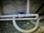
What I don't like about the design is that instead of having a valve near the skimmer (closer to us) that blocks ALL water flow to the heater pipes, the only way to shut it off completely is via 2 valves about 20 feet away, on the 2 vertical pipes leading up to the heater. (He also added two drain valves on the piping along the ground which was a good option to add). There is a valve near the skimmers (see pic) that we can turn off so the water coming back from the filter has to flow left... but I don't understand it.
With the old design, on a sunny day when I turned on the pump, I immediately felt a surge of warm (even hot) water going into the pool from the return because water was standing in the solar panels for the past few hours; with this design it doesn't seem as warm. Also, with the old design we could use the Turtle with the heater on, but the pressure would be a little weaker; with this new design, the Turtle barely moves if the valve near the skimmer is closed (pushing the water to the solar heater), so we have to choose between cleaning or heating.
Other than that it's hard to explain the concept so I am attaching a picture.
I am hoping someone who knows more can confirm to me that this design really is fine, and it's just me not understanding water pressure/flow etc.
Thanks much!
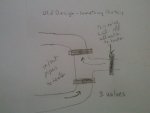
(I can provide a rough diagram of the previous design if needed)
edited a few times for typos, clarification.
When we first got our solar heater, my husband designed a pipe lay out that made sense & worked well. There was a valve close to the skimmer/filter area that we could turn off to block all water going to/from the pipes leading to the solar heater. This worked out great when we had a leak in the panels or when the water was warm enough, and we would turn it off when using the Polaris Turtle to clean the pool so we had full pressure.
My husband wanted to move the pipe location, and a couple parts cracked. So he took it apart for the winter and decided to have a plumber redesign / install the piping. We explained how it was done before, but the plumber designed it differently. It didn't make sense to me, but hey, I'm not a plumber and I don't know all the ins & outs re water pressure. :?
What I don't like about the design is that instead of having a valve near the skimmer (closer to us) that blocks ALL water flow to the heater pipes, the only way to shut it off completely is via 2 valves about 20 feet away, on the 2 vertical pipes leading up to the heater. (He also added two drain valves on the piping along the ground which was a good option to add). There is a valve near the skimmers (see pic) that we can turn off so the water coming back from the filter has to flow left... but I don't understand it.
With the old design, on a sunny day when I turned on the pump, I immediately felt a surge of warm (even hot) water going into the pool from the return because water was standing in the solar panels for the past few hours; with this design it doesn't seem as warm. Also, with the old design we could use the Turtle with the heater on, but the pressure would be a little weaker; with this new design, the Turtle barely moves if the valve near the skimmer is closed (pushing the water to the solar heater), so we have to choose between cleaning or heating.
Other than that it's hard to explain the concept so I am attaching a picture.
I am hoping someone who knows more can confirm to me that this design really is fine, and it's just me not understanding water pressure/flow etc.
Thanks much!
(I can provide a rough diagram of the previous design if needed)
edited a few times for typos, clarification.
")