Solar Plumbing Confusion, Questions

Mar 7, 2012
112
Mountain Brook, AL
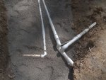
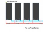
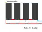
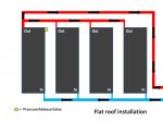
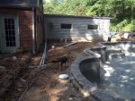
I wanted to post some pics and hopefully get some advice before this is final. I am installing four 4x20 Fafco panels in parallel on a flat roof while my pool is being remodeled. You can see the entire post here - inground-total-redo-going-for-broke-t41950.html

The pool has 1 skimmer, 1 drain, 2 return eyes. It looks like the return line continues around the pool making a full circle back through letter B in picture.

The pool builder made connections today and I will continue from there when I'm sure things are ok.

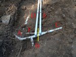
Here is what I think is going on:

A) Water from pump and filter traveling to the right
B) Return line circle from around pool making a loop
C) Return to pool
D) Cold line to solar (New today)
E) Hot line from solar (New today)
F) Never used or plumbed Polaris pipe
(F is not connected to C)
(the buried pipe to the left of the actual letter D is old drainage pipe)

At the siding covered wall where the pipes go up you can just barely see I've installed the cold side check valve. I will install a 3 way diverter valve above it. Then heated and non diverted water will come back down E.

:shock: My main question is does there need to be a total separation at the pipes and elbows of D and E where I have the yellow line? This would make all return water pass through D, then divert whatever % to solar and to return.

If there is no separation then it seems like return water from A and B will go to C and not make it to solar.
These guys are going to want to cover this up soon and work on other stuff so quick advice is very much appreciated.

Thank you!

[attachment=1:3ttuml85]Marked.JPG[/attachment:3ttuml85]
[attachment=0:3ttuml85]7.JPG[/attachment:3ttuml85]
 

Attachments

  • Marked.JPG
    Marked.JPG
    237.5 KB · Views: 403
  • Marked.JPG
    Marked.JPG
    237.5 KB · Views: 396
  • 7.JPG
    7.JPG
    216.6 KB · Views: 396
  • 7.JPG
    7.JPG
    216.6 KB · Views: 396
Whoever plumbed that does not appear to know what they are doing. If left as shown hardly any water will flow through the panels at all. The water will nearly all take the shorter path straight through from A to C.

Typically there is a diverter valve, instead of a T, where pipe D mets the feed from the pool. That location is normally put above ground so the the valve can be adjusted, which needs to be done frequently (either automated or manually). It is also common to have at least one check valve in this area, as well as the shutoffs dayhiker mentioned.

Instead of the diverter valve, you could use a regular ball valve in the line where B is marked, though ball valves don't tend to last as long as a good three way diverter valve.

A third, less efficient but more convenient approach would be to block the pipe off completely at point B, and put the diverter valve over near where the pipes come above ground by the house. That is just as good when running solar, but somewhat less efficient when the solar is off.
 
Thanks for the replies. I do want it right, I'm willing to tear it all out, and I want it to be efficient. I've read so much here to prepare for this but getting someone else to understand is tough. With a project this big you really have to be around a lot and know what is going on or things won't be right.

Here is what I think will make it right:
I believe that all return water needs to pass from A to D. So, I will disconnect E and C at the yellow line and maybe redo that elbow. At the house, D will go to a check valve, then an above ground diverter. The left side of the diverter will elbow up to a ball valve, then to the roof panels. Then warm water will come down E and pass another check valve and ball valve and meet the diverter with a T. Then E will continue through the T and join to the original return line C. It looks like efficiency is lost if it meets back with C at these junctions because of it zigzagging. Should E meet C further up where I placed an X on the other picture? The red O is the first return eye. What would be better than this? Thank you :goodjob:
[attachment=1:2fju1h0x]Marked.JPG[/attachment:2fju1h0x]
[attachment=0:2fju1h0x]Marked 2.jpg[/attachment:2fju1h0x]
 

Attachments

  • Marked.JPG
    Marked.JPG
    237.5 KB · Views: 364
  • Marked.JPG
    Marked.JPG
    237.5 KB · Views: 363
  • Marked 2.jpg
    Marked 2.jpg
    227.5 KB · Views: 361
  • Marked 2.jpg
    Marked 2.jpg
    227.5 KB · Views: 361
I did not follow your thoughts completely but I did not read too closely.

I am wondering about the check valve on the cold solar side. Usually you only have a check valve immediately after the filter and then one on the hot solar return.

Posted with Tapatalk ... sorry if I sound short ... hate typing on phone :)
 
Move the tee for "B" to the other side of the tee for "E". So that B and C are still directly connected.
Put a check valve on A coming from the filter. This check valve protects the filter when the pump turns off.
Put a check valve on E coming from the panels. This check valve keeps water from the panels when solar is off.
Put a diverter where A meets D (and remove the tee). This diverter will select solar or not.
You typically want the diverter near the pool equipment, should you choose to automate the solar.

You could separate D and E as you suggested, and put the diverter closer to the panels. In this case, the check valve still goes anywhere between the filter and the diverter, and the solar return check valve goes on E between the diverter and the panels. Still, B needs to move over to C.
 
Here are some changes that they made this morning.

A now passes through D as a single run.
B joins C.

I hope this is right. The only thing that I'm not sure of is that B and E come in at the same point. That means water from solar is coming south down E and meeting water coming north from B and both are trying to go to C. However, E will have more force as it is the primary feed. I guess I don't understand the circle effect of B as a pressure equalizer. Am I good to go?

Thanks so much for the input!

[attachment=0:2wdrv0kb]100_0257.JPG[/attachment:2wdrv0kb]
 

Attachments

  • 100_0257.JPG
    100_0257.JPG
    107.7 KB · Views: 322
  • 100_0257.JPG
    100_0257.JPG
    107.7 KB · Views: 322
That looks much better. With the appropriate diverter and cheek valve(s) over by the house this will work fine.

Think of B and C as a continuous loop, with E injecting water into the loop. The idea of a plumbing loop is that resistance to flow in the loop is low while resistance to flow in the return fitting is high. As long as that is at least mostly true, the water pressure in the loop will be uniform all the way around and the returns will have balanced flow rates. Without the loop, the more distant returns would have lower flow rates. Your actual pipe run doesn't really look like a loop when you look at the way the fittings are positioned, but that doesn't change the principal of what is going on.
 
Thank you all for the input. I'm glad that part is now right.

Next step is running the lines for the panel plumbing. This diagram represents what I think it should look like.

This is a flat roof install. On the ground level the water will pass from the filter through a check valve and elbow up to the 3 way diverter. Above that, cold water will pass an isolation ball valve, then up to the roof and panels. I have four 4x20 Fafco Solar Bears that have the in and out on the same side. After heating, the water will pass back down the wall through another isolation ball valve, T back into the diverter valve, then rejoin the rest of the return water that didn't go to the panels. No automation at this time. I have built rectangular racks that have one end raised on a slight angle with the plumbing connections being at the low point (the bottom of the angle).

In the diagram the red "Out" lines cross the blue lines, but of course don't tap into them. This was the best I could do in 2D. Any advice is greatly appreciated. Thanks


[attachment=0:exkb72aw]Marked panels 1.jpg[/attachment:exkb72aw]
 

Attachments

  • Marked panels 1.jpg
    Marked panels 1.jpg
    34.8 KB · Views: 275

Enjoying this content?

Support TFP with a donation.

Give Support
Its best to have these plumbed inline, water going into the bottom of all panels on the same line, and then returning from the top, all on one line. If not, you are you not using your panels to their effeciency and will slow down the rate of heat exchange.
 
pooladdict is right about the ideal setup. But some panels come preconfigured to have their input and output on the same end and are not so easily converted to the other arraignment. If you have that kind of panel and don't fell comfortable about reconfiguring them, the setup pictured is reasonable.
 
My panels are marked in and out on the same side. I'm willing to do whatever it takes to make them the best.

There are openings at the other end that have removable caps/plugs. To reconfigure the setup would some plumbing go at the other ends? If that is the case does anything internal need to be changed?

Here is another chart with another option I came up with. It does mostly the same as my first diagram. Thanks for the insight. Maybe I'll change my nickname to BTU hunter.
 

Attachments

  • Marked panels 2.jpg
    Marked panels 2.jpg
    35.5 KB · Views: 243
You do not want to use your new diagram. That is plumbing the panels in series which greatly reduces the efficiency.

To convert the panels over you need to remove the caps from the other end and also remove the diverter disk that is in the inside middle of the header on the end with the original plumbing connections. Once that is done, you feed water in one and and return water from the other end of the panel.
 
If I'm correct the Solar Bear panels have valves on the original plumbing header to divert or not divert the flow through the panel. All you need to do in that case is to follow Jason's suggestions and connect the top (end that's now capped) of all panels together and connect the bottom (end that's now plumbed) of all panels together. Cap the top right end and the bottom left end of the panel group. Open all the diverter valves in the headers. Run the feed in the bottom right and run the return out the top left.
 
Those suggestions will make the setup look just like most of the pics of installations that are on the forum. I just didn't know it was possible with my panels.

I'm trying to fully understand the function of the diverter valve in the header. Jason seemed to say it needs to come out, and Bama Rambler that it just needs to be opened up.

Does the diverter cut the water off at the mid point of the header?

If that is the case then it seems, with it all the way open, the header will fill completely with water and make it all pass from one header (the In side) through all the tubes to the other header (out).

If it is closed then the incoming water will fill half the header, go through half the tubes to reach the other header, and then make its way back through the other half of the tubes to the originating header. Seems reasonable.

When I get home I will take a look and see if/how the diverter disk can come out and reconfigure my drawing plan. The diverter does have a handle to open and close it. I think other Solar Bears have some sort of spring activated valve.

Bama Rambler - Roll Tide!
 
Yes, the diverter blocks water flow in the middle of the header pipe.

The diverters come in a number of different styles. The ones I was describing are plugs that are inserted into the header pipe and need to be pushed out. The kind Bama was talking about, and you appear to have are a valve with a handle you can turn to allow or close off flow from one side of the header to the other.
 
Here is an updated map of the plumbing.

This is based on me turning the header valves open all the way and capping the unused ends. I believe that it is right.

[attachment=0:3mq8ubec]Marked panels.jpg[/attachment:3mq8ubec]
 

Attachments

  • Marked panels.jpg
    Marked panels.jpg
    39.9 KB · Views: 207
To slightly simplify you could connect the headers to each other and just feed from one side and return from opposite side.

Also the vrv in your picture would only really help the 1 panel. Should probably be up on the return.

Posted with Tapatalk ... sorry if I sound short ... hate typing on phone :)
 

Enjoying this content?

Support TFP with a donation.

Give Support
Thread Status
Hello , This thread has been inactive for over 60 days. New postings here are unlikely to be seen or responded to by other members. For better visibility, consider Starting A New Thread.