CPSC48 install

x2rider

0
LifeTime Supporter
Jun 19, 2011
236
Bartlesville, OK
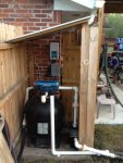
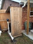
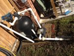
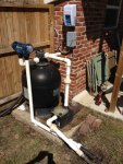
Got my SWG in this week, and spent today hooking it all up.
Will post the final pictures tomorrow of the plumbing redo, the pump was hanging 1/2 way off the concrete slab, so I extended the lines and pushed the filter/pump back closer to the fence.

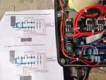
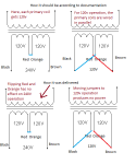
One question though, i moved the jumpers for 120V operation, but the unit is not powering up. I checked the yellow circuit breaker on the bottom, and it's ok. Any ideas? I initially had it hooked to constant power before I realized it was not on the timed power, so it could possibly have turned on before the pump, but it wouldn't turn on after I had the pump running.

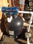
I do need to get a new seal for the pump, it's sucking air. Does the SWG cell ever get completely full of water, or is it always like 1/2 water, 1/2 air with the water looking like a waterfall? The water comes in, and humps up in the center, but so far has not completely submerged the cell.
 

Attachments

  • swg3.JPG
    swg3.JPG
    162.2 KB · Views: 199
  • swg2.JPG
    swg2.JPG
    193.1 KB · Views: 199
  • swg1.JPG
    swg1.JPG
    121 KB · Views: 199
It sounds like you have two different problems. The SWG should power up and show some lights on the control unit when it has power, even if other things are wrong. Also, it sounds like you have a suction side leak. Air must be getting into the plumbing somewhere either at the pump or before the pump. Check to make sure the pump strainer basket lid is on and properly sealing and also that there is plenty of water in the skimmers (if the water is too low in the skimmers they can suck in air.

For the SWG, make sure power is actually getting to the control unit and that the cell cord is properly connected.
 
It's hooked to the timer in the grey box there on the wall. From my breaker, I have white, blue (hooked to breaker), and green. I did use spade connectors on the wires because the stranded wires won't stay in with the solids. I'll check the spade connectors and make sure they are making contact, and if that doesn't work I'll hook it up to a plug and plug it into a cord to see if it'll turn on. At first it was wired directly to the power coming from the breaker, not the switched side of the timer.

To top it off, the breaker decided to break on me and not turn on anymore, so I'll have to get a new breaker tomorrow.

The lid on the pump is leaking, I looked at the seal, and it's not pretty, and it's only a year or 2 old. I really don't like these types of lids/seals on these kinds of pumps.
 
Ok, unit still DOA, but I did notice something.
The documentation doesn't match how the unit is wired up on 2 wires internally.

According to the documentation, the RED wire is supposed to connect to J11, and the ORANGE wire should be connected to J14, but inside, the RED wire is on the J14 and the ORANGE wire is on J11.

Even for 240V, the wires are swapped top to bottom according to documentation.
 

Attachments

  • swg_complete.JPG
    swg_complete.JPG
    181.6 KB · Views: 177
  • swg_cpsc48_wiring.JPG
    swg_cpsc48_wiring.JPG
    143.6 KB · Views: 177
Now that I've thought about it, it makes sense. If those 2 wires are swapped then I have one side of the primary on neutral and the other side on hot so the transformer wouldn't do anything, but even being swapped wired for 240, it would have worked.
 
I'll give them a call, they deliver these things setup for 240v operation, so it would have tested good at the factory.

My pump/timer is all 120V.

To visually show what is going on, see the picture below.
The top 2 pics are how the transformer should be wired. In 240V operation, the 2 primary coils are wired in series so that each of them gets 120V. For 120V operation, the coils need to be wired in parallel, which matches the manual.

The bottom 2 pics is how they shipped this one out. By flipping where they put the Red and Orange wire (Red actually on J8, orange on J12), when I follow the instructions to move them to the jumpers, the unit is now wired where each end of each primary coil is on a leg of it's own, therefore doing nothing. The circuit is completely open.

The instructions say to move the Red Wire from J12 to J11, but hey... Red is on J8! and Orange is on J12, thus the confusion.
 

Attachments

  • Miswire.png
    Miswire.png
    28.6 KB · Views: 157
I'm really glad you posted this because if you got a unit wired this way then at some point someone else will and it'd be a nightmare trying to explain it to customer support. Even if you send it for repair they might convert it back to 240v to test it and it'd work.
 

Enjoying this content?

Support TFP with a donation.

Give Support
Measured salt level 2260, so I got 8 bags of pellets and put 7 in. A few hours later the pellets are almost gone, the unit is still saying low. I did turn it up to 50% and I'm seeing what looks like smoke or fog Inside so I think it's working.

Cya was 70 last Sunday before we got about 4-5 inches of rain last week which put the level from below the top step to 1/2" into the skimmer.

FC 3.8
Cya is now 40! :)

Wonder what it will read in the morning, I may have to bring the level way down esp this time of year.
 
It takes salt a while to mix in throughly. Because of that we recommend running the pump continuously for 24 hours after a salt addition. It probably doesn't actually require the full 24 hours, and the total time could be broken up into several segments, with the pump off in-between, but it is simpler and quicker if it is all done at once.

Separately from getting the salt to mix in throughly, the SWG averages the salt level over 24 hours. So it's reading won't stabilize until after the salt is throughly mixed into the water.
 
Cust Service says that bar graph on the bottom is a measure of what it's putting out..or set to... so if I run it to 100%, the bar on the bottom should go all the way to the right.

The unit does measure water temp, etc, but the only way to get to that, is to hold the select for 5 min like you were going to set the time, and just cycle through to the end to see the temp.
 
Took some left over fencing and created a shade for the system to help shade the swg controller from the elements, hide the equipment and cut down in pump noise since it is right next to conversation area.

Still need to clean it up and treat it. I may have to raise the roof to get it over the fence for rain, I just threw it together really fast and it got dark on me.

Wifey thinks it looks like an outhouse, I may cut or paint a moon on it.
 

Attachments

  • Outhouse3.jpg
    Outhouse3.jpg
    117.1 KB · Views: 60
  • Outhouse2.jpg
    Outhouse2.jpg
    120.1 KB · Views: 60
  • Outhouse1.jpg
    Outhouse1.jpg
    137.2 KB · Views: 60

Enjoying this content?

Support TFP with a donation.

Give Support
Thread Status
Hello , This thread has been inactive for over 60 days. New postings here are unlikely to be seen or responded to by other members. For better visibility, consider Starting A New Thread.