Dual Speed Pump Wiring Question

Dragun

0
Jan 12, 2012
5
subject: Re: Dual Speed Wiring Question, Posted By Bama Rambler He writes:

“230v motor wiring;
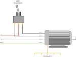
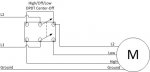
You need a DPDT (Double Pole Double Throw) Center Off switch.
One of the Hot leads goes the the center pole on one side of the switch.
The high speed terminal (L1) goes to one of the side poles on the same side of the switch as the first hot lead.
The low speed terminal (A) goes to the other side pole one the same side of the switch as the first hot lead.
The second hot lead goes to the other side of the switch.
The L2 (Com) terminal wires to one of the switch terminals on the same side of the switch as the second hot.

A jumper needs to be ran between the side poles of the switch terminals that the second hot is going to.

Maybe this drawing will make it a little clearer. Not exactly how I described but close enough. I'd wire it without the first switch (DPST) and break both lines through the DPDT Center Off switch.”

(It has an image placeholder but the image is not there)
Anyone know where I might find this pic?

My question is:

Since this refers to a DPDT switch, and I have a GE outdoor 15087 time switch that can be configured as a DPDT, I was wondering if anyone ever tried to do the above with a time switch like the GE 15087. It is selectable to 120vac/240vac/277vac

The reason is I have an AO Smith B2982, and I cant afford expensive timer and this only cost 55 bucks. I read somewhere in here that someone did this with a simple flip DPDT switch.

I‘ll post the pump label. Any ideas would be greatly appreciated. BTW this is a great site.
I’m can take this timer back since it’s still boxed. I suppose a timer that has 3 circuits would be best but what to buy that will hurt the least? I have been working on this for about 2.5 weeks and I’m afraid to look under the pool cover. There are probably creatures growing in there by now.

I tried to upload the pic of the pump label but it wouldn't let me.
 
The proper answer may depend upon what you wish to accomplish. If you want the timer to simply switch between lo and hi, but not turn the motor off at all, then you can wire the timer to do that. If you want to have the timer switch the pump on and off, and manually select the pump speed with a toggle switch, we can help with that, too.

Let us know how you'd like this to operate.
 
Here's the drawing of the hookup I was describing in the old post.
wiring-230v-pump.gif
 
OK Thanks. This is great info. Thanks all. Now I am going to take all the info, cram it into my head, turn it around so that I can bring it into focus, and make a drawing that will, hopefully, work. I will let you all know what I come up with, and see what you think, before I stick my finger in the socket. JK
 
Being in a similar boat (I'm considering a two-speed pump for the replacement I'm about to do), could I use something like an Intermatic 153 to run the main pump as a two-speed and run the Polaris booster? I don't need fancy as I have no other loads to deal with, and this Intermatic claims to be three-circuit...
 
For clarification, if I may, I would like to go back to square one and ask a question without consideration of any HI - LO switch in the circuit..

Keeping in mind that according to my AO Smith B2982 connection diagram , L1=HI, L2=COM, and A=LO.

Here is my confusion. In my old motor, a WFE3 .75 HP 1ph 1sp, the 240v are coming from the panel on two HOT 120v wires and were connected to L1 and L2. The third wire was connected to the little metal access door/panel opening on the WFE3 pump housing which in this unit is essentially the same as ground since the grounding lug is also connected to the housing. I traced the third wire to the pool panel where it was connected to a common bus and that bus has a copper strap that is tied to the cinder block wall. One might conclude, from that, that it is therfore the ground bus. I mean what else could it be?

My question then is, where do I put the third wire? I think on A=LO and not the green (ground) screw. My confusion comes from the third wire going from A=LO to the pool panel bus which I THINK is also the common (ground).

To further confuse me, I also read in the GE quick start guide for the 15087 time switch under Definitions of Terms, it says: "COM contact is switched between the Normally-Open and the Normally-Closed contacts. This is not “AC Common” or neutral." What??????

I think, I’m over thinking it, but I want to be safe and I don’t want to fry the new motor. I could not trace “the common” line between the pool panel and the house panel and read that these are suppose to stay separate. Is this true? If so, I suppose thats so that if the pool panel fries it does not take the house panel down with it?

Does this site have a glossary of terms so I can read more about how to view the terms, ground, common, and neutral, in relation to pump motors and pool panels? Or a link to a site that has info to read about this?
 
You’re right ohm boy. This is not the place to learn those things and I second those warnings to anyone reading this. I learned those in school and then in my jobs as a bench tech, a computer and network system tech, and too many others to mention. True I don’t know the electricians codes, but I’m not asking about codes. I’m asking for ideas and bounce back on what appears to me to be contradictory or confusing information. I’m sure you are familiar with the saying “everybody knows something, but nobody knows everything”. So thanks for the warning. I may follow your recommendation if it gets hard. I’m not there yet. For the record, yes I am well aware of the very real dangers.
 

Enjoying this content?

Support TFP with a donation.

Give Support
I agree with Ohm Boy and as long as everybody agrees to heed the warning I'll dive into a little explanation.
Dragun said:
For clarification, if I may, I would like to go back to square one and ask a question without consideration of any HI - LO switch in the circuit..

Keeping in mind that according to my AO Smith B2982 connection diagram , L1=HI, L2=COM, and A=LO.

Here is my confusion. In my old motor, a WFE3 .75 HP 1ph 1sp, the 240v are coming from the panel on two HOT 120v wires and were connected to L1 and L2. The third wire was connected to the little metal access door/panel opening on the WFE3 pump housing which in this unit is essentially the same as ground since the grounding lug is also connected to the housing. I traced the third wire to the pool panel where it was connected to a common bus and that bus has a copper strap that is tied to the cinder block wall. One might conclude, from that, that it is therfore the ground bus. I mean what else could it be??
You are right the third wire (which should be green) is equipment ground.

Dragun said:
My question then is, where do I put the third wire? I think on A=LO and not the green (ground) screw. My confusion comes from the third wire going from A=LO to the pool panel bus which I THINK is also the common (ground).
In a 230 volt high/low speed situation, you will have 3 wires from the power panel. L1, L2 & Ground. L1 will go to the common side of the hi/lo switch, L2 will go to motor "COM" and Ground will go to the ground (green) screw. From the switch you will have one wire going from the "HI" lug to L1 on the motor and another going from the "LO" lug to A on the motor.

Dragun said:
To further confuse me, I also read in the GE quick start guide for the 15087 time switch under Definitions of Terms, it says: "COM contact is switched between the Normally-Open and the Normally-Closed contacts. This is not “AC Common” or neutral." What??????).??
What it states is completely true. "COM" on the timer is NOT neutral. In relay circuitry "COM" is the connection that's common to both N.O. and N.C. terminals of the same circuit. It is NOT ground or neutral!

Dragun said:
I think, I’m over thinking it, but I want to be safe and I don’t want to fry the new motor. I could not trace “the common” line between the pool panel and the house panel and read that these are suppose to stay separate. Is this true? If so, I suppose thats so that if the pool panel fries it does not take the house panel down with it?
Not just picking on you, but what we need to do is STOP calling the ground or neutral conductor "common"! If we would call them what they are, it'd cut down on a lot of confusion.

Dragun said:
Does this site have a glossary of terms so I can read more about how to view the terms, ground, common, and neutral, in relation to pump motors and pool panels? Or a link to a site that has info to read about this?
That's a job for an electrical forum. You can go to an electrical forum and learn all you never wanted to know
 
OK, Just for info...
Here is a basic diagram for using a double-throw switch (it's called out as a DPDT, but could be SPDT since only one side is used) to select low or high speed for a motor. This does not provide start/stop control, only the ability to select a speed.[attachment=1:1d0c5uvz]Hi-Low_DPDT.jpg[/attachment:1d0c5uvz]

Using a DPDT Center-Off switch, one can add on/off control as well, as shown in this schematic.[attachment=0:1d0c5uvz]Hi-Low-On-Off_DPDT.jpg[/attachment:1d0c5uvz]
 

Attachments

  • Hi-Low_DPDT.jpg
    Hi-Low_DPDT.jpg
    26.4 KB · Views: 279
  • Hi-Low-On-Off_DPDT.jpg
    Hi-Low-On-Off_DPDT.jpg
    15.5 KB · Views: 276
Dunno if this will help anyone, but here are some search links for 20 amp DPDT center-off toggle switches from Grainger, Digikey, and Mouser. And for those in Orlando, Skycraft.

Grainger search DPDT ON-OFF-ON Motor-rated, 20A
http://www.grainger.com/Grainger/wwg/se ... 4293703197

Digikey search (toggle switches) DPDT ON-OFF-ON 20A
http://search.digikey.com/us/en/cat/swi ... 0On-Off-On

Mouser search (toggle switches) DPDT ON-OFF-ON 20A
http://www.mouser.com/Electromechanical ... 0A&FS=True

Skycraft Surplus DPDT On-Off-On 20A
http://www.skycraftsurplus.com/search.a ... Off-On+20A
 
So....I just picked up a Superflo 1 HP 2-speed and an Intermatic P153. The pump came with the manual switch on the power end, I assume to switch between high and low speeds. Should I wire up with the switch on "high" or disable/remove the switch? Surprisingly, the install/O&M paperwork does not address this...
 
Thread Status
Hello , This thread has been inactive for over 60 days. New postings here are unlikely to be seen or responded to by other members. For better visibility, consider Starting A New Thread.