Main breaker worked on, now pump wont turn on

May 24, 2011
30
Austin, TX
All,

An electrician came out and worked on my main breaker box installing two new circuits. The next day I found my pool pump no longer turns on. I hear the relay click but there is no noise from the pump at all. He claims he didn't do anything that would effect the pool but nothing else has changed on an otherwise stable configuration. My config:

- Goldline Pro Logic (PL-PS-8) with Hayward 1/3 hp pump (label says 230/115v).
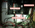
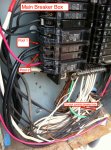
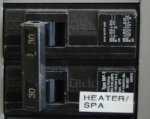
- Main breaker box has two breakers that go to the pool control box
- Measuring breaker 1 to ground shows 120v, same for breaker 2
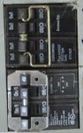
- Inside the pool control box there are two blacks coming in each read 120v to ground. To each other there is nothing.

Any idea what might have changed? The electrician claims whatever he did should not effect the pool. The only thing I can think of is the pool is suppose to be getting 240v but something changed and it isn't. But then again I have no idea how to check if this is the case.

At any rate if he can't figure it out tomorrow I am going to have him call a pool guy on his dime!

Thanks in advance.
 
Your profile doesn't indicate whether you're in North America or not, but I'm going to assume that your power is delivered North American style (240V center-tap, two legs which are each 120V to neutral, but 240V leg-to-leg).

Is your pump wired for 230V or 115?

When you say you have "two breakers that go to the pool control box" are these two separate breakers that were/are tied together with a bar so that if one of them trips, it pulls the other? You would find an arrangement on this powering subpanels or appliances that require 230V. Each of the two halves of the breaker would be on opposite legs.

What I'm thinking here is that your pool control box is supposed to be receiving 240V power (two circuits on opposite legs, 240V leg-to-leg and 120V leg-to-ground) but the breakers were moved around in your main panel so that now both halves are receiving the same leg (0V leg-to-leg, 120V leg-to-ground). This will definitely require some electrical knowledge to fix. Maybe start with a picture of your main breaker panel with a label showing which one goes to the pool box...
 
Thanks for the response adelman!

- I am North American (Austin, TX)
- I don't know if the pump is wired for 230V or not. How can I tell?
- In the main breaker box there are two breakers that go to the pool but no they are not tied together with a bar (see picture)
- In the pool controls box there are two breakers that are tied together with a bar (30A each)
- I can confirm the two black wires coming into the pool control box have 120V to ground, and 0V to each other.

See attached pictures. Let me know if I can provide other views / more information.
 

Attachments

  • poolpanel.jpg
    poolpanel.jpg
    142.9 KB · Views: 109
  • main_breaker.jpg
    main_breaker.jpg
    161.9 KB · Views: 109
Did he change the breakers going to pool1 and pool2? What you're showing is a split breaker which feeds from the same stab in the panel so it feeds 120 volts from the same phase to both breakers. You can't get 240 from it. From the pictures your pool panel needs 240.
 
In the current setup (from the picture) I know the breakers above and below the pool breakers are new. I do not know what the configuration was before the work was done. I can ask.

Is the breaker type wrong or is the placement wrong, or both? Perhaps this information is enough to have him fix it. He claims he knows nothing about how the pool should work and that he changed nothing that would effect it. Of course that isn't right otherwise it would work. =)
 
Ok. Take a look at the backbone "bus bars" of the pool breaker box. If you look carefully, you'll see that there are protruding blades that the breakers connect to. Notice how the lowest blade is from the left bus bar and if you were to put a breaker into either the vacant lower left or vacant lower right slot it would connect to this bar. The next blade up is from the right side bar (the other leg of the 240V) and breakers here, in either the left or right side, connect to the right side bar. Your main panel is of the same construction, even though you might not be able to see the blades. The way a 240V (aka 2-pole) breaker works is to hit two of these blades FROM OPPOSITE LEGS (i.e., 240V leg-to-leg).

Your pool subpanel is definitely a 240V type, and you should have 240V leg-to-leg on those incoming wires. This is further confirmed by the presence of the inter-tied 2-pole breaker (which I assume, feeds the pump). Your pump isn't working because you're feeding two legs which are 0V leg-to-leg.

Given that you had the main breaker changed, one of the first things I'd check is that you indeed have 240V leg-to-leg on the main panel. Do you have other 240V equipment in the house? Electric oven or clothes dryer? Do they work? Can you physically access the left and right bus bars on the main
panel anywhere to touch a meter to them and confirm the 240V leg-to-leg?

However, the above questions are really just things I'd want to confirm. The problem is apparent in the picture. If you look at the physical size of the lowest, left breaker, that is a "normal" single-pole (120V) breaker. The one above it is a special breaker designed to fit two *independent* circuits into the same physical slot, for when you have a crowded panel and need room. That duplex breaker only can grab one blade, so the output will ALWAYS be 0V leg-to-leg!!! Check this. You *positive* those are the wires going to the pool? Confirm by turning that breaker off and be sure you now have 0V leg-to-ground on both legs at the pool panel.

For some reason, the guy who did your main breaker had to do some "minor" reorganization of your panel. Either he was a total idiot, or more likely, these was already a violation in the way the panel was wired and he didn't understand that those two wires were opposite legs of a 220V. For example, if they were fed from two breakers on opposite legs which weren't physically tied together, moving them would have seemed like a harmless change. It is more than moving breakers, the wires must have been moved from a different breaker because that type of breaker can never put out 240V (since it only accesses one leg).

I'd get him back there. Unless I knew you better, I'm hesitant to say this is a DIY project (only 'cause it can kill you). I have a lot of experience around this sort of stuff, but am not a licensed electrician. The correct fix is basically to figure out what must have happened by reviewing the entire panel. Either you have a proper
240V 2-pole breaker of the correct size that isn't being used for that anymore, in which case wires need to be traded back, or you never had one (and one is going to need to be added). Adding one is going to mean moving some other breakers around, and perhaps replacing some of the single breakers with doubles
to make room. All the breakers need to be sized correctly, and I suspect a review of all of the circuits in the panel is in order.

Ken
 
A "proper" 240V breaker has a mechanical connection between the two poles, so that if one of them trips from an overload, it pulls the other half off at the same time. This is usually a pin that connects the two adjacent switches. Looking at that picture some more, it almost looks like there is such a pin connecting the two halves of that breaker. Is that the case? You should never have a pin on that type of breaker, because those two halves are always on the same leg and can't give you 240V. A 240V breaker is always physically bigger because it needs to engage two legs.

If there is a pin, then it was put there on purpose, and since it previously worked, we know it was put there on purpose by the last electrician to touch it. If that is the case, the guy is an absolute idiot with no understanding of how this works, and I suspect, not a licensed electrician either.

If there is no pin, I would give the guy's intelligence the benefit of the doubt. Perhaps the wires were previously incorrectly connect to two different breakers which were not intertied with a pin, so he didn't realize that they were two halves of a 240V circuit when he moved them. The real curiosity is why this changed.

Pin or no pin?
 
Ok, I reread your original post. For some reason, I thought you said the electrician changed the main house breaker, in which case, it made no sense that he would touch this area. It the breakers above and below are new, it is more obvious what happened; he removed what was there in order to make room for the new circuits. Did he leave the old breaker behind? Picture, please.

BUT, the real reason I'm writing this post is that I see a potential other problem (with his work). The breaker above and below the pool breaker would be on the same leg (since every other tab is on the same leg). I see a RED wire on one and a BLACK wire on the other; do these go into a common piece of Romex? This is a common technique called "three wire wiring" where two circuits share a common neutral (white) wire in the Romex. You run two "HOTS" and one white wire in one Romex wire to save cost. It is VERY VERY important that the two circuits be on OPPOSITE legs so the current in the neutral subtracts, rather than adds, to prevent overloading the neutral without tripping a breaker. If those two wires (and because of the color, I suspect so), go into the same Romex, you could overload the neutral in your wall and start a fire.

For the same reason, you should keep the pool breaker off until this is fixed. The 120V circuits in your pool panel could, in theory, overload the neutral if they drew enough
power (I doubt they would).
 
Those 2 black wires going to the pool panel (120v to ground, 0v to each other) should have 240v to each other.

It appears to me that there were two full size breakers side-by-side (should have been connected together by a bar or pin and act as a single unit) which fed the pool before your 'electrician' worked on it, and he removed one of them, and replaced it with a dual breaker (two half size units in one full size body). in order to gain an additional circuit. The kicker is that he claims that nothing he did could have affected the pool.

In my humble opinion, this guy isn't qualified to connect Christmas lights, much less wire a pool service. I strongly suggest that you find another electrician and have him redo this.
 

Enjoying this content?

Support TFP with a donation.

Give Support
To give you an idea of what he did in other terms, it's as if you called a locksmith to change your front door lock and he put the keyhole on the inside of the door.

This is clearly not the work of a pro.
 
Hmmm... That breaker looks ok to me. It does look a lot like a single phase double breaker but there's a pin between the switches and it's rated 40A which wouldn't be the case if it was the same phase on both sides. Either way the thing to do would be to test the incoming power termianls at the pool subpanel. You'll either get 220v as you'd hope, 0v with 120v to ground (both legs same phase) or 120v if something is really wacky (one hot line, one neutral/ground potential).
 
[attachment=1:3ilarx3e]_DSC1530.JPG[/attachment:3ilarx3e][attachment=0:3ilarx3e]_DSC1531.JPG[/attachment:3ilarx3e]
crumley said:
Wow, thank you everyone for the great advice. The work is being done by a sub contractor. I called the general and he is going to send a real electrician to fix it.

Again thanks so much for the help!

Ask the real electrician to inspect everything this guy did. He should open each of the receptacles and anything else he accessed for a quick inspection for safety and code compliance.

The 30A breaker in the picture attached is the style that you likely originally had feeding the pool subpanel. The breaker must be sized to protect both the subpanel and the wire. Note that this breaker is tall enough to attach to two of the tabs and therefore access each phase of the 240.

The other two breakers (50A/40A) in the second picture are (each) the same height of the 30A breaker in the first picture. These access two of the tabs; the top two switches are on one phase, and the bottom two are on another. These are used when you run out of panel room... In my installation they are each being used for two 240V circuits, BUT you can using a wire cutter and remove the tie that connects the outer two and use them for two 110V and one 240V circuit.

I just want to show you this so you know what to expect from the real electrician. IF those two new circuits share a common neutral wire, then they must be on opposite phases. Assuming we don't want to move anything else in the panel, the only way to make this work is going to be to use one of these double-double breakers and cut the intertie from the top and bottom of the four switches.
 

Attachments

  • _DSC1530.JPG
    _DSC1530.JPG
    63.5 KB · Views: 71
  • _DSC1531.JPG
    _DSC1531.JPG
    42.3 KB · Views: 71
The electrician came out this morning and rearranged the breakers so that the two new circuits are on different phases (the circuits that share the same neutral). He did the same for the pool circuits and tied the switches together with a pin.

Now everything is working and should pass inspection.

Thank you everyone for all the advice and safety tips. If the pool pump continued to work I bet this work wouldn't have been reviewed and I would be worse off for it. Thanks and happy holidays!
 
Thread Status
Hello , This thread has been inactive for over 60 days. New postings here are unlikely to be seen or responded to by other members. For better visibility, consider Starting A New Thread.