Pool-light won't turn on --- HELP!!

Aug 3, 2011
99
Hey all --

So my pool light has never worked (moved in a 1.5 yrs ago). The bulb/gasket has been replaced, there's no water in the light fixture.

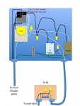
Over at the equipment pad, on the timer box, there's an electrical outlet... that gives no power at all. I know it's wired to work... there's a flood light nearby that's supposed to hook up to this outlet. On the outlet itself, there are two little circles: one red and one black, that look like they should be fuse-related... or like the GCI type outlets you usually find in bathrooms... except they don't push-in or anything. None of my friends have ever seen this type of thing before. I assume the outlet not providing juice is related to the pool-light not working.

Anyone have experience dealing with this? I'd like to fix it without calling an electrician.

On the face of the timer box, you can see the fuse switches (two red, one blue). There's also a little white-ish button down on the lower right corner, near the outlet.


Got frustrated and opened up the box...

Found a more standard looking GCI type outlet inside, with a test and reset button. Looks beat to all heck. Resetting didn't help anything. :(


(unplugged the black cord for the closeup)
 
First off..I assume you have turned off the power to this panel at your main house panel.....you've got 220 volts out in the open. The "fuse switches" are called circuit breakers. The 2 red switches are acually connected together so they switch on or off together. This is a typical arrangement for a 220 volt branch. As best I can tell from your pictures, the 2 black wires coming out the left side of this breaker, go to the timer relay. And I am assuming that the 2 yellow wire nuts connect the relay outputs (blacks) to the red wires that go thru the conduit to your pump. This is a 220 volt circuit. The blue circuit breaker is a single handle, hence it is a 110 volt breaker. However, there is nothing connected to the screw terminal on the right side of this breaker. Hence, none of your 110 volt stuff is getting any power. To remedy the situation, you need to connect a black wire from the breaker to "something". I can't reliably tell you what that something is, since I cannot figure out what all those outlets and switches are suposed to do. I believe the outlets are both GFICs...maybe so old they don't work. The push button switch looks like one of those X10 home automation system switches..the red & black dials are to set a specific "address". If you don't have any other X10 stuff, you can replace it with a regular switch.
I know I haven't given you the ultimate answer, but I hope I've clarified things a bit. And if you haven't worked around electrical panels much, PLEASE BE CAREFULL and turn off the power to this panel....this stuff can easily kill you.
 
Hi Ed, I appreciate the response. Yes, I cut off the power before messing around. :)

And you definitely clarified something. I too noticed the blue breaker didn't have anything connected to it... At least you gave some confirmation to what the problem may be stemming from.

If you notice in the 1st pic, in the first post -- there's a small box a few feet under the panel, that wires run thru. Inside that little box, are 4 wires, 2 of them are connected via wire-nut... the other two are just hanging out, loose.

Probably too many possible problems for me to fix on my own (why so many loose wires? Something must be messed up -- there's another loose wire in the 1st pic of the 2nd post, under the push-button switch)... I'll call an electrician tomorrow.
 
Good move JP. The outlets loose in the box look like a disaster waiting to happen. What someone that does it every day can do in an hour or two will take you a day or two by the time you run for parts a few times and everything else.
 
A pretty shoddy job the way the wiring inside the panel was done. Very dangerous. ed0846's post is correct about the X10 stuff. Both the pushbutton switch (that probably controls the pool lights) and the receptacle on the side are X10 controlled. X10 is an older home automation protocol that allows you to control the system remotely with your computer, remote controls, etc. When it works, it is pretty slick, but there are better alternatives (like Insteon or Z-Wave). It also looks like someone decided to add GCFI protection to one of the circuits (probably the pool lights) by running a hotwire from the Intermatic timer terminal to a GFCI receptacle (dangerously unmounted), and then snip off an extension cable to plug the pool light X10 circuit into. Instead, it would have been far better to provide a GFCI circuit breaker, or even an in-line GFCI for the light. But, these are more expensive. In any event, I would just replace the whole thing with a newer panel and/or control system. Pentair has a Suntouch system and Intermatic has a new system that is controlled by Z-Wave. Either of these can automate simple pool setups (including valve actuators so you don't have to go back to the equipment pad to switch between pool vs. spa, etc). I would strongly suggest getting this fixed before someone gets hurt.
 
If you DIY, probably no more that about $50 in parts and some reasonable knowledge of electricity and your local building codes. Probably around $30 for a single pole GFCI breaker that you would use to run your lights circuit off of. You could do a direct replacement of both the X10 pushbutton switch and the receptacle for another $20 or so (see x10pro.com). If you don't care or need the X10 control, those parts would probably be around $10 or so at your local HD. I'd guestimate around $150-200 for an electrician to do the work for you (using the existing panel), though they likely wouldn't have the X10 stuff on hand if you want to go that route.
 
It looks like a pretty easy fix, esp. for an electrician. But from the view provided, I can see the 220V line in with 2 line wires (both black), neutral (white) and ground (green) coming up from the left rear conduit and connecting to the line lugs on either side of this 2P circuit breaker (meaning no main breaker; that is on the main circuit breaker panel). A 220V/20A breaker feeds the input side of the timer, along with a neutral. In front of that is the pump conduit with two switched black wires coming from the timer connected to two red wires by wire nuts, and a green ground wire connected to the grounding terminal. The blue 1P breaker is probably rated for 15A, and was likely there for the light circuit and the accessory outlet. When it was re-wired to add the GFCI, it appears that this breaker was not used. I can't tell from the pictures if the person who did this took the line input to the GFCI from one of the black wires entering the timer, or if it was originally wired to the blue breaker. In any event, when re-wiring, replace the blue breaker with a 15A GFCI breaker (with the white coiled wire on the breaker wired to neutral via a wire nut). Completely remove the added GFCI outlet and extension cord end, and unwire the outlet and switch. Both of those typically have wires instead of screw terminals, so add a black wire to the terminal of the new GFCI breaker to connect to the line (black) wires of the switch and the outlet. I don't see a neutral bar, so you will have to draw the neutral from either the neutral terminal on the timer, or splice the neutral line using a wire nut to white wire to feed the outlet and light circuit.

BTW, I believe the box below the panel you describe is the pool light junction box. If you remove the top, you should see two sets of three wires inside (plus bonding wires if they were run). In the flexible conduit coming out of the panel, you should have a black, white and green, and these should be connected to similar wires that run to your 120V pool light. Is this correct? A picture would be helpful. Also, if you could take a pic of the panel after removing the GFCI outlet, that would help.
 
Small subpanels are cheap. I would change the panel as well. You can leave yourself a little expansion room and gain a neutral bar and enter the modern world. If you bring in an electrician the panel might pay for itself in labor saving just because when you have him start saving the old panel he might add in a little extra labor in case he runs into problems.
 

Enjoying this content?

Support TFP with a donation.

Give Support
Thanks for the great replies, guys!

Here's a pic of that little box of wires --- looks like I remembered incorrectly... there are more wires in there then I thought, just as Craig suggested. The pic will follow below (I'm not brave enough to remove the GFCI just yet)...

Could it be so simple as to attach the two white wires, and the black and yellow wires? When we moved in, the pool light was half-flooded with water. Maybe rather then replace the bulb/gasket they just removed the power to the light?

Any reason you guys can come up with as to why there's a white wire loose of the black extension cord piece (the one you can see when looking that white push-button)? I assume that's the same loose white wire down in the little box in the image below.

 
The hole on the right of the junction box plate appears to be from the flex conduit coming from the panel. The hole on the back of the plate appears to be routed to the light conduit itself. Ground wires from each are connected to ground terminals on the plate, which is fine. The light fixture appears to have black (load), white (neutral) and green (ground) as it should. The conduit to the panel has yellow (load), white (neutral) and green (ground). It would be good to verify this in the panel. In addition, I still can't see in the panel behind the GFCI and the pushbutton switch, so I can't tell how they wired it (e.g. is GFCI first or second there).

In any event, either get a new panel as suggested, or get a GFCI breaker to replace the blue one, then run a black wire to the load of that breaker to the line side of the pushbutton switch and the side outlet. Take neutral from the white wire entering into the timer, and ground both to the grounding terminal. After verifying that yellow is indeed the load wire in the pool light junction box, use wire nuts to connect the loads (yellow to black) and neutrals (white to white). I think the previous owner disconnected the wires in the light junction box after observing water entering into the light fixture as a safety precaution. Who knows why this person removed the load wire from the 15A 1P breaker?
 
CraigMW said:
The hole on the right of the junction box plate appears to be from the flex conduit coming from the panel. The hole on the back of the plate appears to be routed to the light conduit itself. Ground wires from each are connected to ground terminals on the plate, which is fine. The light fixture appears to have black (load), white (neutral) and green (ground) as it should. The conduit to the panel has yellow (load), white (neutral) and green (ground). It would be good to verify this in the panel. In addition, I still can't see in the panel behind the GFCI and the pushbutton switch, so I can't tell how they wired it (e.g. is GFCI first or second there).

In any event, either get a new panel as suggested, or get a GFCI breaker to replace the blue one, then run a black wire to the load of that breaker to the line side of the pushbutton switch and the side outlet. Take neutral from the white wire entering into the timer, and ground both to the grounding terminal. After verifying that yellow is indeed the load wire in the pool light junction box, use wire nuts to connect the loads (yellow to black) and neutrals (white to white). I think the previous owner disconnected the wires in the light junction box after observing water entering into the light fixture as a safety precaution. Who knows why this person removed the load wire from the 15A 1P breaker?

LOL --- I'm an idiot sometimes. I getchya now. I'll go out right now and take some better pics of the GFCI area.

Would you mind if I keep picking your brain on this --- I'm actually getting the 'picture' now, so I think I can pull this of on my own, with your help. :)
 
Okay, it appears that the extension cord end is spliced to the wires that go to the pool light junction box (PLJB). Thus, the GFCI receptacle is wired after the X10 pushbutton switch. BTW, that switch, an X10 Pro PLW01, is shown here:

http://www.x10pro.com/pro/pdf/plw01.pdf

First off, you need to make sure this panel is not energized before you do any work. Shut off its breaker at the main panel on the house. Next, you should get yourself a voltage tester of some sort, either a neon electric tester, or better yet, a digital VOM. These can be obtained from HD for less than $20. I would strongly suggest getting some extra 12 gauge copper wire (black, white and green). You only need a few feet of each. Stranded is okay, but better would be solid core. Also get some plastic wire ties that you can use to tidy up the installation.

You can purchase a direct replacement if needed, and they are pretty cheap. There should be two wires coming out of this (and perhaps a grounding wire or screw). The black is connected to the line (e.g. the black wire that should come off the new GFCI breaker that I strongly suggest you purchase and use to replace the current blue breaker). The blue wire on the PLW01 is to be connected to the load side (e.g. the yellow wire that goes to the PLJB). The neutral (white) wire from the PLJB should be connected to a white neutral in the box. It appears there is an extra one of these hanging off the right side of the timer. I don't know that timer but it looks like that white wire is being used as a neutral elsewhere. If not, pigtail (e.g. use a wire nut) off the white neutral wire entering the panel along with the two black wires that energize the breaker buses. Make sure to run a green ground wire to the unit if there is a place to do so (though it may be grounded because it is screwed directly into the panel).

The receptacle on the side appears to be an X10 Pro PAO11, with info about it here:

http://www.x10pro.com/pro/pdf/pao11.pdf

This receptacle has two outlets, one of which is switched on and off by an X10 remote, the other should be always on. You can replace this with a standard 15A receptacle, or keep it if it is still functional. It has three wires, a black (line), white (neutral) and green (ground). Connect the black wire to a new black wire pigtailed off the load wire that is screwed into the new GFCI breaker. Connect the white wire to the pigtailed neutral white wire, and run an extra green ground wire to the green wire on the receptacle and connect them with a wire nut.

In the PLJB, use wire nuts to connect the yellow wire to the black wire, and then connect the white wires together in the same manner.

I'll upload a schematic of what I'm talking about shortly.
 
Awesome -- I'll re-read and make sure I understand every step before I get started.

I forgot to mention earlier... That I have no use for the home-automation stuff, so I'd like the hardware to be as simple as possible.

I searched Lowe's website for a GFCI Breaker -- and could only come up with the outlets. Their website has been notoriously bad for hardware searches for me in the past though. They must have one in-store? I do have HD and ACE nearby as well.

I can probably get started on the work on Thursday --- so no big rush to dig up info. :)

Thanks again for all the help.
 
Here's another question --- Could I run an extension cord from a normal (functioning) outlet and plug the pool light in that to see if it works?

I wonder because that white wire is loose (the one that is coming out of the black extension cord piece), it probably wouldn't work.
 
Then get one of these so you have remote control: http://www.x10.com/automation/x10_rc6500.htm

This gives you remote control over the pool lights and the flood lights. As for testing the pool light to see if it is operational, I don't really see how that helps as you are going to have to have it rewired anyway. You should use your multimeter or voltage checker to see if, after rewiring, the switch is still functional (e.g. a 120V difference between the blue wire and a neutral exists) after tapping on it (make sure the button below the main one is not pushed in, as it opens the circuit for light bulb changing.
 
Wow, great chart --- thank you so much!!! You rock, dude!

The light testing, I will admit -- was just to satisfy my curiosity. The kid in me wanted to see the light turn on. :)

Can't wait to get started on this Thursday... I'll check back and let you know how it goes.
 

Enjoying this content?

Support TFP with a donation.

Give Support
Thread Status
Hello , This thread has been inactive for over 60 days. New postings here are unlikely to be seen or responded to by other members. For better visibility, consider Starting A New Thread.