Hook up our heater?

fordfampool

0
LifeTime Supporter
Jun 9, 2011
44
Wisconsin
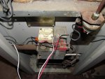
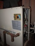
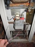
Can anyone offer any suggestions to help us hook up our heater? The pool guy came over in May and started it by jumping it. It "ran" for a bit but the pool wasn't ready to be heated so it was turned off. Then last week we had an electrician out to make sure all was up to code and he discovered the wires under the floor boards in the shed had been chewed up. He replaced them and now this is what we have (see pix)

Do we just get the pool guy back out to hook it up, or is this something we can do? Thanks, for any advice you have!
 

Attachments

  • IMG_0376.JPG
    IMG_0376.JPG
    85.1 KB · Views: 195
  • IMG_0374.JPG
    IMG_0374.JPG
    41.6 KB · Views: 175
  • IMG_0379.JPG
    IMG_0379.JPG
    69.4 KB · Views: 175
From the pictures you supplied, I see two points of concern. First, a ground wire is ominously missing. I only see a red and white wire coming in through the PVC conduit. Second, there is no rubber grommet protecting the wiring that enters into the cabinet of the heater. That bare metal hole could damage the wiring if the wiring is tugged on in this serviceable part of the heater.

I would have the electrician back out to install a grounded line to the heater (is this 120 or 220V, BTW?). Second, I would have him provide some protection to the wiring, either by adding a grommet to the bare metal of the cabinet, or run the conduit into the cabinet. Lastly, make sure he adds GFCI breakers to ALL of your electrical pool equipment. Lack of ground and lack of ground fault protection could easily kill someone.
 
Thanks for the tip on the grommet. I'll do something about that myself.

This is a low voltage wire that is coming from the pool timer box, so no ground is needed (the timer itself is grounded). GFI outlets have been installed, they are just not in the pics.

I am thinking that these two wires will need to be hooked up to two of the three electrical points shown on the heater, just not certain.

Thanks,
Mike
 
fordfampool said:
Yes, it is a RayPak. The thermostat is on the side. SO, maybe that is our answer! I'll check that out.


Raypack Gemini 150 I think.

See the orange wire nut on the left of the gas valve?

Unscrew that wire nut and a split up the 2 wires. Attach one of them to the white, and the other to the red. It doesn't matter which one goes where.
 
fordfampool said:
Thanks for the tip on the grommet. I'll do something about that myself.

This is a low voltage wire that is coming from the pool timer box, so no ground is needed (the timer itself is grounded). GFI outlets have been installed, they are just not in the pics.

I am thinking that these two wires will need to be hooked up to two of the three electrical points shown on the heater, just not certain.

Thanks,
Mike

Okay, good to know those are not high voltage lines. I guess the timer box has the millivolt lines from the heater's gas valve connected to separate poles on the timer. Does this timer also control the pump?

From the picture, it looks like this is a Raypak Gemini 3. You might look for the actual model number on the heater and then look here for more info:

http://www.raypak.com/FTP_View.cfm?FTP_MainCategory=P
 
racket,
You are a genius! I did exactly as you suggested and it fired right up!!!

CraigMW,
Yep, it is a Raypak Gemini 3. The timer does also control the pump. I found that link to the manuals prior and the parts listing, but I never found a wiring diagram. Thanks though!

Thanks for the tips everyone!!
Another score for TFP and it's awesome user base :)
 
Um - I may be wrong but here goes
That definitely is low voltage wiring and since your heater has a thermostat built in I am pretty sure those wires lead to your timer and are part of the "FIREMANS" circuit. This allows the timer to shut off the heater 20 minutes before it shuts off the pump to avoid overheating the water in the heater after the water stops flowing. It is VERY important that those 2 wires be connected to the FIREMANS Switch connection on the heater, not to the terminals on the gas valve. If you connect them to the gas valve directly you will in effect be making the complete circuit and bypassing the safety switches that protect the heater from overheating and overpressure. It is still a DIY job but do a search for your heater and find an old wiring diagram to help you find the right place to connect those wires.
 
Thread Status
Hello , This thread has been inactive for over 60 days. New postings here are unlikely to be seen or responded to by other members. For better visibility, consider Starting A New Thread.