Low flow from LQ SOLVED! on AGP w/pics

DonW

0
Jun 27, 2008
97
Central IL.
This might be of use to folks who have a 2 speed pump (or anyone that doesn't, like myself) and wants to get their LQ to flow without having to to adjust the skimmer valve. It also may be old news for some, but it is new to me.
I don't know how many people were silently suffering with a no/low flow problem from their LQ on their above ground pools like I was, but the problem was deemed unacceptable and I knew there had to be a solution. I scoured the LQ board and came across a hint from mas985, author of "Hydraulics 101 - Have you lost your head?", and much other fine information in the "Pumping Station" section.

He said
"...a very short (< 6") section of smaller diameter pipe which would simulate a venturi. The injection point would be in the smaller pipe.

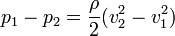
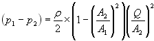
The venturi concept relies upon the fact that pressure will drop when water velocity increases. So by downsizing the pipe for a short section, you will get a pressure drop (more suction) but it is temporary unlike head loss with a valve is. The pressure rises once again once the pipe expands back to the original size."

Well thank you Giovanni Battista Venturi the Italian physicist for your discovery, and to mas985 for suggesting it. It works! I went from NO flow, to a reading of 4.5 with the venturi injection. My pump pressure before the mod was 11, afterwards was 10~10.5. OoRahh!! Plus the fact that the LQ is operating as advertised! I've reduced the 1 1/2 inch pipe down to 3/4 inch for approx a 6 inch span.


DSC00848.jpg

DSC00849.jpg

DSC00856.jpg

DSC00855.jpg
 
DonW,

I have been trying to fix that very same issue with mine...your solution looks promising.

One question:

How does that 6" reduction to 1" differ from kepping the skimmer valve partially closed, does it not restrict water flow in the same manner?

actually two:

Do you now keep the skimmer valve fully open?

Thanks again for your idea...Bo
 
Robins Airman, The reduction is 1 1/2" to 3/4". I don't fully know the answer except what mas985 had stated: "...you will get a pressure drop (more suction) but it is temporary unlike head loss with a valve is". A physicist or hydraulics guy I'm not, beer drinker yes. I guess that it restricts the water flow only over those 6 inches, and then it picks back up again.

I suspose that the end result in my case was the same in regards to pump pressure. Before the mod I'd partially close off the skimmer valve to artificially create suction, dropping my pump pressure by one pound. After the mod with the skimmer valve wide open, I have enough suction but again pump pressure had dropped by one pound. So is there a real difference? The jury is out, but at least the LQ is operating without the aid of the partially closed skimmer valve which for some reason I hated. With the skimmer valve wide open, I have achieved enough suction to draw from the LQ and the concept works like it was intended. Did I trade a partially closed valve for $5 worth of PVC? Maybe, but I'm a little bit happier now. Good luck to you. Try it, it'll work!
 
DonW said:
Robins Airman, The reduction is 1 1/2" to 3/4". I don't fully know the answer except what mas985 had stated: "...you will get a pressure drop (more suction) but it is temporary unlike head loss with a valve is". A physicist or hydraulics guy I'm not, beer drinker yes. I guess that it restricts the water flow only over those 6 inches, and then it picks back up again.

I suspose that the end result in my case was the same in regards to pump pressure. Before the mod I'd partially close off the skimmer valve to artificially create suction, dropping my pump pressure by one pound. After the mod with the skimmer valve wide open, I have enough suction but again pump pressure had dropped by one pound. So is there a real difference? The jury is out, but at least the LQ is operating without the aid of the partially closed skimmer valve which for some reason I hated. With the skimmer valve wide open, I have achieved enough suction to draw from the LQ and the concept works like it was intended. Did I trade a partially closed valve for $5 worth of PVC? Maybe, but I'm a little bit happier now. Good luck to you. Try it, it'll work!

Thanks Brother, I think I will and post results...Bo
 
It's got to do with energy. The principle of conservation of energy is that energy cannot be created nor destroyed, it can only change state. Water flowing through a pipe only has a certain amount of energy packed into its pressure, velocity, and temperature. If any of these three properties change then none of both of the others has to change as well.

We'll ignore temperature although it does change with pressure...

The water in your pipe has a certain amount of power calculated as total energy = Pressure x Flow

Pressure is Potential Energy. It can do work but is not actually doing anything.
Flow is Kinetic Energy. It is energy that is doing work.

If you completely close a circ pump discharge the flow rate is zero so the water has zero kinetic energy. However, the water pressure rises to around 30 PSI (whatever the max of your centrifugal pump is) which is all potential energy. That water could do work but it's being held back by a valve.

Now you open the valve fully and the discharge water pressure drops to around 10 PSI - 2/3 of the potential energy has change state to kinetic energy and it's doing work - moving water. That water has both kinetic and potential energy in it but the total energy doesn't change. The principle of Conservation of Energy states that energy can neither be created nor destroyed, it can only change state.

(the purist will point out that the closed valve situation has less energy in the water than the open valve situation and if they want to they can go through the hassle of calculating losses to heat, vibration, noise, entropy, and whatever else cause I ain't gonna!)

We don't know your flow rate so lets set an arbitrary rate of 100 USGPM. This is the flow rate/total energy state that doesn't change throughout your suction line that we'll use to figure out velocities and pressures. Since this is the suction side the pressures are likely to be below atmospheric. Usually we refer to that as vacuum and express it in inches of mercury but you can also use Absolute Pressure (PSIA) and, in fact, calculating this stuff requires we talk absolute pressure

To get 100 GPM through a 1.5" pipe the water has to travel at about 18 feet per second and that flow rate requires a pressure of 10 PSIA

To get 100 GPM through a .75" pipe the water has to travel at about 72 feet per second, but what pressure does that require?

The energy number in the water before the restriction is 10 PSIA * 18 FPS = 180 PSI/FPS. Energy cannot be created or destroyed so the energy number inside the 3/4 inch pipe still has to be 180. The velocity has to go up to 72 fps to get the 100 GPM flow rate in a 3/4 inch pipe so the pressure must go down.

180 PSI/FPS = 72 FPS x X PSIA
X PSIA = 180PSIA/FPS / 72 FPS = 2.5 PSIA

Inside the 3/4 inch pipe the pressure would be 2.5 PSIA or about a 25 inch vacuum.

Once the pipe widens again the velocity drops and the pressure rises.

Now, I'm not exactly sure what was meant by "temporary compared to a valve" because the exact same principles apply to a partially closed valve. If it is close to a 3/4" opening then it'll have the same velocity and pressure at that point. The difference being the valve can be re-opened which removes the restriction, raises the pressure, and increases the flow rate.

Placing the 3/4 pipe did decrease the flow rate through the system which is evident by the drop in discharge pressure. The drop in flow rate will be proportional to the drop in discharge pressure So if you went from 11 PSI discharge (assuming clean filter etc etc) to 10 PSI only because of the change AND the flow rate after the change is the (guessed at) 100 PSI then the old flow rate would have been about 100 GPM / 10 PSI = X GPM / 11 PSI = 100 * 11 / 10 = 110 GPM.

Now those are the changes in flow rates in "ideal" conditions. A pipe reduction usually creates less turbulence than a valve restriction so it's not quite as detrimental to flow rates but in real world applications there's usually not much of a difference.
 

Enjoying this content?

Support TFP with a donation.

Give Support
PatM said:
We don't know your flow rate so lets set an arbitrary rate of 100 USGPM. This is the flow rate/total energy state that doesn't change throughout your suction line that we'll use to figure out velocities and pressures. Since this is the suction side the pressures are likely to be below atmospheric. Usually we refer to that as vacuum and express it in inches of mercury but you can also use Absolute Pressure (PSIA) and, in fact, calculating this stuff requires we talk absolute pressure

To get 100 GPM through a 1.5" pipe the water has to travel at about 18 feet per second and that flow rate requires a pressure of 10 PSIA

To get 100 GPM through a .75" pipe the water has to travel at about 72 feet per second, but what pressure does that require?

The energy number in the water before the restriction is 10 PSIA * 18 FPS = 180 PSI/FPS. Energy cannot be created or destroyed so the energy number inside the 3/4 inch pipe still has to be 180. The velocity has to go up to 72 fps to get the 100 GPM flow rate in a 3/4 inch pipe so the pressure must go down.

180 PSI/FPS = 72 FPS x X PSIA
X PSIA = 180PSIA/FPS / 72 FPS = 2.5 PSIA

Inside the 3/4 inch pipe the pressure would be 2.5 PSIA or about a 25 inch vacuum.
Your information is incorrect. You cannot simply multiply the pressure by the velocity. You are also using incompatible units.

Here are the correct formulas:

d19a4c05f53604e2284e959c24a1c175.png

http://upload.wikimedia.org/math/d/1/9/ ... a1c175.png

http://en.wikipedia.org/wiki/Venturi_effect

i_venturi_pressure_differential.png

http://www.ajdesigner.com/venturi/i_ven ... ential.png

For 40 gpm going from 1.5 inch diameter pipe to 3/4 inch pipe there would be a pressure drop of about 5.3 to 5.5 psi.

Here is a calculator that will do the calculation for you.

When doing the calculation, you need to use compatible units. I use:
Pressure in Newtons per square meter. Density of water = 1,000 Kg per cubic meter. Velocity in meters per second. Flow rate in cubic meters per second. Area in square meters.

Example: 40 gpm going through 1.5 inch ID pipe = 7.27 feet per second and going through 0.75 inch pipe equals a velocity of 29.06

7.27 feet per second = 2.216 meters per second
29.06 feet per second = 8.857 meters per second

P1 - P2 = 1000/2(8.8572 - 2.2162) = 38,115 N/M2 = 5.53 psi.

Also, the pressure needed to move a given amount of water through a pipe (straight horizontal pipe of one diameter) depends on the length. You cannot just say that it takes 10 psi to create a flow rate of 100 gpm through a 1.5 inch diameter pipe.

Furthermore, putting a flow rate of 100 gpm through 1.5 inch and 3/4 inch plumbing is not realistic, especially on suction, as in this example. The calculated pressure drop would be 33 psi, which is not even possible.

A 6 inch section of 3/4-inch PVC will create about two feet of head loss (40 gpm), which is about 0.9 psi added to the suction head, which will be deducted from the pressure side head loss.
 
It is good to see that reality matches theory.

[EDIT] Ignore what I had wrote before. JamesW pointed out that it wouldn't work. Rising the LQ would solve the problem but that has it's own issues.
 
If you reduced from 1.5 inch I.D to 1 inch I.D, you would get about 1.44 psi of pressure drop (3.33 feet of head), which should be enough (at 40 gpm). A flow rate higher than 40 gpm would create more pressure drop.

Flow gpm.............PSI drop.............feet of head

40.......................1.44.......................3.3
50.......................2.25.......................5.2
60.......................3.25.......................7.5
70.......................4.4.......................10.2

If the flow rate is less than 40 gpm, then a reduction from 1.5 inch to 3/4 inch would be needed.

Flow gpm.............PSI drop.............feet of head

10.........................0.33.......................0.77
20.........................1.3.........................3.1
30.........................3.0.........................6.9
40.........................5.33*....................12.3

If you have a two-speed pump, then it's more complicated, because what would work at one speed might not work at the other speed.

Another alternative is to raise the Liquidator to above the pool water level. This will put the Liquidator at a lower pressure and allow the liquid chlorine to flow. The Liquidator would not necessarily need to be near the equipment, because the flow is so slow. You could use tubing or PVC pipe from an elevated platform to the equipment.

*[edit]Calculated using the "nominal" I.D of the PVC pipe. Using the actual I.Ds (Inside Diameters) of the PVC pipes gives a pressure drop of 3.63 psi. The actual I.D of 1.5-inch PVC pipe is 1.610 inches, and the actual ID of 3/4-inch PVC is 0.824.[end edit]
 
The original idea was to create a pressure drop without much head loss but after a little analysis, I am not so sure there is much benefit. I did a quick calculation of the head loss through a contraction, a tee and an expansion for 1.5" pipe and 3/4" fittings @ 40 GPM.

Contraction: -1.27 PSI
TEE: -1.87 PSI
Expansion: -2.12 PSI

Venturi Effect: -3.63 PSI

Pressure at injection point: -5.83 PSI (Contraction, 1/2 of tee and Venturi effect)
Total pressure loss of fittings: -5.26 PSI

So the head loss of the fittings creates about the same pressure change as the head loss of 1/2 the fittings and the venturi pressure drop. So it would work just as well if the injection point was after the expansion and you might end up with less head loss by using the skimmer valve instead.

With a 1" TEE in the middle it is a little better:

Contraction: -0.4 PSI
TEE: -0.67 PSI
Expansion: -0.49 PSI

Venturi Effect: -1.22 PSI

Pressure at injection point: -1.95 PSI
Total pressure loss of fittings: -1.56 PSI

In each case, the head loss from the fittings is probably enough to get negative pressure at the pump so in reality the Venturi may not be adding much of a benefit. However, a real Venturi with smooth transitions might result in more suction and less head loss.

[EDIT] Found some errors in the calculations. It changed the results slightly.
 
I can not tell a lie...you all lost me at contraction... :?

i dont know which way to go now...leave it or make the reduction to 1"...i am worried that if reducing wont work i will have to replace that section of PVC...not a big deal...just more work and my honey-do is long enough already... :shock: :lol:

Thoughts?

Thanks...Bo
 
My main point is that using a reduced diameter tee as a venturi will probably have about the same head loss as using a valve at the skimmer. The valve at the skimmer is easier to install, less intrusive and is adjustable. So my recommendation would be to not go this route. It will work fine as in DonW's case but it offers very little benefit over a simply valve.

As was pointed out by JamesW, elevating the LQ will also work although that can be hard to do and keep stable.
 
mas985 said:
My main point is that using a reduced diameter tee as a venturi will probably have about the same head loss as using a valve at the skimmer. The valve at the skimmer is easier to install, less intrusive and is adjustable. So my recommendation would be to not go this route. It will work fine as in DonW's case but it offers very little benefit over a simply valve.

As was pointed out by JamesW, elevating the LQ will also work although that can be hard to do and keep stable.


Thank you...i think i will leave it alone...for now.

Bo
 
Thanks to the pros in the know for clarifying everything. It appears that the jury is back and there is no real benefit from the modified venturi injection point over retardation of the skimmer valve. I CAN say that I am very happy with the outcome of the mod. Before the reduction, I had zero suction at the strainer basket drain and absoutely hated the idea of closing off the skimmer valve to create it. I had lost prime to the LQ twice and the flow gauge required daily tweaks. It is true that the reduction has caused a 1 pound pressure loss - equal to closing off the skimmer valve to achieve flow. But now, I have tons of flow, the flow gauge is consistent and steady, and the LQ is working as advertised. Special thanks to mas985 for the idea - my open skimmer valve & I thank you!
 

Enjoying this content?

Support TFP with a donation.

Give Support
Thread Status
Hello , This thread has been inactive for over 60 days. New postings here are unlikely to be seen or responded to by other members. For better visibility, consider Starting A New Thread.