Re: Need Help with Motor Replacement Electrical Wires
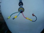
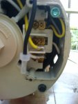
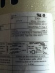
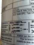
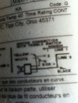
On you motor will be a wiring diagram actually. You simply follow the directions in it. Motors can be wired either high or low volt ( 240-110). Determine what your old motor was wired by either using a multimeter on your wire ends ( it's ac...no need to worry about polarity) or have a look at the wiring diagram on your old motor. To switch between high or low on them is a matter of moving one wire from one terminal to another. It'll be colour coded on the diagram ( Just an example and this may not reflect this new motor of yours: b/wtracer on terminal 3 for high volt or b/wtracer on terminal 4 for low). Your two big posts/terminals are for your load. If you have three wires, one being green, the black and the white are your loads ( I see that yours are not coded normally). They can go on either motor load terminal. Green goes to your ground screw, located off to the side just under the cover. Some motors come factory wired high volt ( should be a tag or card inside that states that if it is) and you'll need to read that motor diagram to move the right internal wire onto the correct terminal ( all colour coded and numbered) of you have 110 volts on the motor circuit. Some motors, like replacements from Hayward have a plastic terminal block you move to the appropriate slot, no tools required.
Bottom line: Find out your pump circuit voltage first, consult the motor diagram, determine if you need to change the motor's current internal wiring on the board and then hook up your ground and loads.