Here's how I would test the system. This is me, and I wouldn't recommend anyone else try this. Especially without parental supervision... I don't want to be held liable if someone electrocutes themselves. If you don't know electricity, it can happen. Hire a licensed electrician.
I would put the controller in service mode and turn pump off at controller. IF the controller still has power when the pump breaker is off, turn the pump breaker off. This is the way the controller should be wired - although every once and a while I run across one that uses the AC from the pump breaker to also power the controller. The following assumes that the pump breaker does not power the controller.
I would then test the voltage to the relay:
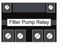
Top two contacts are from the control board and control the on/off of the relay. For purpose of this troubleshooting, I will call these contacts 1 and 2. I will use the term "leads" to describe the test leads of the meter.
Using an ohm/voltage meter - I would ground one lead of the meter (there should be a green screw inside the bottom of the control power center), and then put the other lead of the meter onto either one of these contacts. I would put the meter on "Volts AC" mode.
I would hope to read 0 VAC (or very close) when the the pump button on the controller is off.
I would then turn the pump on at the controller - I should read ~24 VAC at these points (ground screw, points 1 or 2, using the meter leads) when the pump is on. This "24VAC" is the signal the controller gives the relay to turn on the pump. It should be 24VAC when the controller is on.
I would then turn the pump off/on several times and verify that the 24 VAC appears when the controller is trying to turn on the pump, and that ~ 0VAC is there when the controller is telling the pump it should be off.
Diagnosis:
If it works as expected, then I'll move to the other side of the relay.
I should also hear ONE clicking sound each time the relay engages, dis-engages. If I hear click-click-click-clickkkkkkkkk (etc...), I would make sure the VAC is right - if it is, I have a bad relay. If the 24VAC (or something over a few volts AC) remains on the meter when the pump has been turned off via the controller, I likely have a bad control board in the Jandy.
Assuming this test passed....
Testing the bottom of the relay:
Again, I would double-check that power to the pump is off at the breaker, but the controller still has power. Pump should be "off" also at the controller.
I would put the meter in "Ohm" mode.
I would put one lead of the meter on the far-left bottom connection on the relay. I would put the other lead of the meter on the bottom-second-from-left connection on the relay. I will call these points 3 and 4 IN THAT ORDER (and the last two on the right side will be 5 and 6).
I would verify that there is "Infinite" ohms between these two points (it might read several M-ohms - Pump is off at the controller - pump breaker is off as well).
I would turn the pump "On" at the controller (but leave the pump breaker off) - I would hope to read close to 0 (1-2) ohms between these two points.
I would turn the pump on/off at the controller several times and verify that the relay gives me infinite ohms (or is in the M-Ohm range) when the controller is trying to turn on the pump, and 0 (or ~1-2) ohms when the relay (pump at the controller) is on.
I would then test points 5 and 6 the same way.
If 3/4 and 5/6 both are infinite/M-ohms when the controller is telling the pump to be off, and 0 (~1-2) ohms when the controller is telling the pump to turn on, then the relay SHOULD be good.
If not, I likely have a bad relay (Remember, I have already verified that the control board is sending me the right voltage, 24VAC, to the relay at the right times - pump on = 24VAC at 1/2, pump off = 0VAC at 1/2).
Assuming I haven't found a fault to this point (power breaker to pump is still off - assumes 220VAC operation, using points 3/4 and 5/6. If the pump is wired for 120VAC operation, then only 3/4 OR 5/6 should be used):
I would verify that the wire connected to contact 3 is coming from the control-center's breaker that controls the pump.
I would verify that the wire connected to contact 4 goes to the pump.
I would verify that the wire connected to contact 5 is coming from the control-center's breaker for the pump - and that indeed it is a breaker config for 240V - in other words, the lead coming from contacts 3 and 5 are on different contacts on the breaker.
I would verify that the wire connected to contact 6 is going to the pump.
I won't discuss pump wiring, as I would expect it to be correct - at-least until all else fails.
I would turn the pump off at the controller.
I would turn the breaker on for the pump.
There is a green ground-screw in the bottom of the box. I would put the meter in VAC mode.
I would put one lead on the ground screw and one lead on contact 3 - it should read 120VAC (yes, 120). I would put one lead on contact 5 and leave the other on the ground screw - again, it should read 120VAC.
I would leave one lead on ground and check contacts 4, and then 6 - they should both read 0VAC (or, very, very close to 0).
Put one lead on contact 3 and one lead on contact 5 - should read 240 VAC.
Put one lead on contact 4 and one lead on contact 6 - should read 0VAC (or very very close to 0).
Turn the pump on at the controller. Make sure meter is still in VAC mode.
One lead at contact 4 and one lead at ground should read 120VAC.
One lead at contact 6 and one lead at ground should read 120VAC.
One lead at contact 4 and one lead at contact 6 should read 240 VAC.
Turn the pump off at the controller - these three readings should go back to zero (or, very close).
If the power at contacts 4/6 is 220VAC when the pump is on and the relay is engaged, it should be off when the relay is dis-engaged.
If I've verified that the relay is good, and the power is good, and I'm still having problems - I'll turn everything off and go have a beer while I scratch my head for a long, long while...