Swg-no power

Aug 10, 2016
7
Gulfport, MS
Good evening, all!

I converted my pool to a salt water system a month ago. We moved into the house we just bought, and have been renovating the pool system. I replaced the pool motor since it was frozen, and added the SWG system (Hayward Aquarite Goldline T-Cell-3). It worked great for the last month or so. Last week, I went to check on the generator after work (my wife is home during the day, so I try to start it every morning before work and have her turn it off after 8 hrs). We had had a lot of hot afternoons combined with a lot of rain, so I'd been letting stay on longer to get our chlorine level up to where it should be. I also had just started to implement stabilizer a week ago as well, and the first couple days went well.

When I checked on the generator, the pump was still running, but the generator was completely off. No LCD display, no lights at all. I checked the power with my mulitimeter, still around 240 volts, as it normally is. I read up on it, and found out that the resistor (quarter sized black thing) is a common issue, as well as the 20amp fuse. Replaced the fuse with a brand new one that I tested with both a fuse tester and my multimeter, no luck. Moved on to the resistor. I tested it, resistance was low: around .7 instead of 2 ohms. I got the replacement piece today from Amazon (I did try the other site as well, but longer shipping). Soldered the new resistor on, and it seemed ok. I checked it with the multimeter, it sits right at 2 ohms. The generator still appears to have no power. I checked and rechecked my wires, and none seemed to have bad contacts. I tried the voltage again, still 240. Tried the fuse again, still ok. I also have not found any burn points on the circuit board. Does anyone have any ideas what is going wrong?? Brand new system! Is there anywhere else on the board I can test to see where the failure is?

I have no idea what to do! I truly appreciate anyone being able to get back to me. I shouldn't have had this issue only a month after buying this brand new system!!

tl;dr: month old, brand new SWG, no power after heat wave/thunderstorms. Fuse and resistor are fine, no effect after replacing.

The forum won't let me add pictures, so please see below... And I'll try to reply to this post with pictures.

Model looks like this:
Amazon.com: Hayward GLX-PCB-RITE Replacement Main PCB Printed Circuit Board for Hayward Goldline AquaRite Salt Chlorination Systems: Patio, Lawn Garden

Amazon.com: Hayward GLX-PCB-DSP Display PCB Replacement for Select Hayward Salt Chlorine Generators: Patio, Lawn Garden
 
Welcome!

I read more about this PCB and that round thing is indeed resistor of sort, called 'inrush current limiter' with purpose to limit current spike when you connect it to 220V power. It gets normally hot and its resistance drops to low value so it kind of 'disappears' from the circuit. It also seems over time Hayward boards suffered from this element overheating and eventually failing. I don't think this is your case as board is new and it showed low resistance in your test.

OTOH you mentioned thunderstorms close in time in the area and that often causes electronics to fail. I never fixed this kind of boards before so it's hard for me to make any recommendation remotely. In any event if simple checks tracing power wires to the board don't show up the problem like blown fuse I'd advise to replace the board as from description it sounds like the system lost the power and this board is responsible for that.

Element level troubleshooting requires a lot of experience and it involves working on the board under power so I highly recommend NOT to do that.
 
Thanks for the quick reply, max2k!

What elements can I test besides the thermistor and fuse? Since the voltage is just fine, in addition to these elements, I have the electrical experience to work with the board under power. I grew up learning a lot about electricity and how to work with it since my dad's an electrician, and have worked with quite a bit of live wires in my house. I also have a multimeter and a voltage tester to make sure I don't touch anything with a current.

Anyone have any suggestions? I'm desperate to not have to replace both of the PCBs. Especially after not having it for even a full month. There are no burn marks anywhere, so it doesn't seem to suggest that there was an overload in voltage that I can tell.

Why both boards? In the worst case I'd still expect the display board to be fine, it just doesn't get any power. Do you see any secondary voltages present? If not I'd replace the power board.
 
Why both boards? In the worst case I'd still expect the display board to be fine, it just doesn't get any power. Do you see any secondary voltages present? If not I'd replace the power board.


Oh, nevermind! I thought that that's what you were suggesting. Are there any other elements I can test on the power PCB? For one, where to test the voltage being supplied to the display PCB?
 
Oh, nevermind! I thought that that's what you were suggesting. Are there any other elements I can test on the power PCB? For one, where to test the voltage being supplied to the display PCB?

OK, I watched few videos about this board and it looks like it doesn't get 110/220 V AC directly, there's transformer in front of it. Please check voltage rating on big capacitors to make sure, it seems they're rated to 35V which is much safer to work with. I'd also check if the board is getting AC voltage from the transformer. Unfortunately I never worked with these boards so I can't tell you what voltage to expect but my guess would be something like 36V AC. The point is to check if it is present at all.

There's small fuse on the right bottom edge of the board itself between those 2 big capacitors- did you check if it is OK?

I think I found the issue, or at least narrowed it down. I did test the fuse, it was ok. Both of the capacitors measured 70 exactly... I'm guessing this is because they are wired together, and I can't take them off of the board to measure separately. I found this Hayward diagnostic manual while I was searching for how to test the transformer

http://www.prolinedist.com/wp-content/uploads/GL-AQR-Disgnostic-Manual-r1.58-2011.pdf

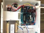
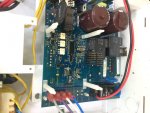
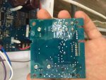
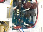
I followed the entire diagnostic flowchart for the No LED's/LCD Display portion (starting on page 12 of the .pdf). The last step had me test the DC voltage going to the Display PCB, and it read 0 instead of the 3-5 it mentioned. I tried to reseat the DSP PCB, but it still won't work. The next plan is to follow up with Hayward again regarding the warranty, and see if they'll replace the DSP PCB. I'll also see if a local shop can test it in store to verify my findings. Below are some pictures of the board and affected portion.

image1.jpgimage2.jpgimage3.jpg

- - - Updated - - -

Sorry for the orientation... They're normal on my computer, but rotated once they posted.
 
did you see 31.7 V DC voltage between red & black wires as shown on p12 of that manual (next to the black round resistor you were trying to replace before)? This is main input voltage for the board as I understand. It sounds like you measured 70V DC on the capacitors if so it confirms the fuse, black round resistor are fine and board is getting input power from the transformer.

Do not remove capacitors or any other elements from the board, you can damage them or the board in the process. The troubleshooting manual does not contain tests for any secondary DC voltages except that 3-5 V test. Since you measured 0V there I'd suspect the main board does not produce power and should be replaced. The display board is most likely fine, it's just not getting power from the main board. I'd check voltages on small silver cylindrical electrolytic capacitors on the main board to see if any of them have any DC voltage. If none are present then it would re- confirm that the main PCB needs replacement.

Please be careful, the board still has section connected to 110/240V. That section is also powered by black & red wires through the contact bar with small screws. That section is marked with word PRIMARY.

I did, yes. It was within the threshold on page 12, in the low 30s but below 33. Which are the silver capacitors that you mentioned? I can't seem to locate them. Unless you mean the one that is next to the fuse, and not the two large ones?

- - - Updated - - -

Ah, did you mean the two small ones behind where the display PCB sits? If so, what voltages should I be getting? 3-5?
 
Instead of all this diagnostic work how about a warranty claim? Either from whom you purchased or directly from Hayward. Hayward has a one year limited warranty.

I see little utility in doing all this work when there is a warranty out there that you paid for.
 

Enjoying this content?

Support TFP with a donation.

Give Support
Instead of all this diagnostic work how about a warranty claim? Either from whom you purchased or directly from Hayward. Hayward has a one year limited warranty.

I see little utility in doing all this work when there is a warranty out there that you paid for.

Ha, that is exactly what I'll be doing... It's just that the local certified Hayward repair shops don't want to do on-site work, and have only offered for me to buy replacement parts. I have to wait until after the weekend to call Hayward again about it.

- - - Updated - - -

I'm just trying to diagnose in the meantime to make sure that the repair person doesn't try to replace more than they need to, and potentially try to charge me for it.

- - - Updated - - -

the ones circled in red below. I'd expect to see 5V DC on those:

Ah, that's what I was thinking. Thank you, I'll test those next and get back with the results!
 
I checked both of the capacitors, with the bottom left, labeled C6, (bottom right in the picture) measuring 0.728 VDC, and the top right one, labeled C7, (top left in the picture) not showing any current. It looks like those might be the main issue, and would definitely require a replaced board. Hopefully Hayward will follow through on the warranty!
 
Thread Status
Hello , This thread has been inactive for over 60 days. New postings here are unlikely to be seen or responded to by other members. For better visibility, consider Starting A New Thread.