Intermatic Pool Timer Wiring

Mar 28, 2016
12
Austin
I have a timer that does not seem to work correctly. The manual on off switch does not work, the pump is always on. The timer works, just not the switch. At first I thought I had a bad timer and bought a new one to replace it. The same behavior was happening on the new one as the old one.

I recently had an electrician replace the conduit going from the pump to the timer. I am now thinking maybe he did not wire it correctly.

I have a 103R Intermatic which is the 120v dpst.

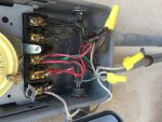
Does this wiring look correct? Do I really have 120 or 220 going to the timer?
IMG_6103.jpgIMG_6104.jpg
 
Looks like 220V to me. Can you note which conduit goes where?

- - - Updated - - -

From the instruction manual it looks like one of the RED and BLACK wires were swapped.

- - - Updated - - -

Usually there is a drawing on the inside of the front cover. Does yours have that?
 
jmpilon, I'm going to :bump: your thread for more views/activity. Rather than us try to make assumptions about your pump based on the pic of the wiring (which is a bit difficult to figure-out all wired so closely), we really should be going from the pump to the timer. So you should update your pump info into your signature. This way we can look-up your make/model pump, review its "specs", and see how it "should" be wired. In addition, there should be a label on your pump motor that indicates what type of voltage it is. I think working from that direction would be best. Also, with all that wiring, I'm guessing you have something more than just a pump motor going to that timer. So it would be good to know what else you may have wired to that area.
 
Are you saying the pump cycles on/off with the timer but the switch will not control the pump? Or the timer rotates, but the pump stays on continuously?

The T103R is able to be set up for 120/240 volts. The clock motor of the timer is 120 volts (and appears to be the only item wired correctly). Difficult to tell with that jumble of wires. The breaker in the main panel is a 50 amp 240 volt breaker. In the timer box, it looks like someone connected a black wire to the ground wires, one green ground wire to the white commons and left a white common wire not connected to anything. Not the safest way of doing things.

If it was mine, I'd start over. You may need to check the wiring at the pump and the freeze protection to see if they used standard color conventions. Can you list the number and colors of all wires coming out of each conduit?
You may want to make yourself a basic drawing and show the wiring and colors used. Refer to the link pabeader supplied above for wiring at the timer.

I think the freeze protection is supposed to be hot all the time so it cycles the pump when indicated. Can you provide a picture or technical info on the freeze protection?

Also, please edit your signature to include filter and pump makes/models - this will help us better understand your system.
 
So do I have 220? Is that why 1 black wire is coming from the panel is capped off?

I wonder why they used a 120 timer? Could my pump be 120? Could the freeze protection be 120?

With these questions, I would suggest you get an electrician in there to help you. The pump could be either 120 or 240. The label on the motor will tell you but, it won't tell you which configuration it is set for.
 
Holy smokes! Fire that electrician fast!!

First thing I see, before getting into your main question, is the shoddy code work here. First I see a green wire connected to a couple whites, second I see a black wire connected to your grounds not to mention what looks like a loose green wire in there as well.

What in the world is going on.... From my view, minus the issues already stated, the timer looks to be wired to the pump good so if the pump never turns off you have a defective or somehow activated freeze control as it's bypassing the timer as what it's designed to do. Most have a setting knob to pick the temperature at which it triggers. What you can do is try to locate this knob. If one isn't seen remove the red and black wire from terminal 1 and 3 that head over to the freeze protection from the left side of the timer box. That will disable the freeze control and should put the timer back online. Looks like the supply wires from the breaker and to the pump are solid and the wires from/to the freeze control are stranded.

GL!
 

Enjoying this content?

Support TFP with a donation.

Give Support
Thread Status
Hello , This thread has been inactive for over 60 days. New postings here are unlikely to be seen or responded to by other members. For better visibility, consider Starting A New Thread.