This could be long--sorry in advance.
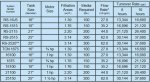
I had a new pool installed last year, and I decided to go with a variable speed pump since it was for one reason or another free for me to upgrade to it. The pump itself is a Viron P280 variable speed pump with speed settings ranging from 1375 RPM to 3075 RPM. Last season, I noticed that occasionally the pump would blow sand (or what I think is sand) back into my pool. When I vacuum on filter, it spits it right back into the pool. I vacuumed on waste, and eventually, I had more in the bottom of the pool. I thought maybe I had cracked laterals, but that doesn't appear to be the case. Recently, I've been doing some research to figure out whether or not this pump, at 3075 RPM (which is it's automatic priming RPM when it turns on each time for 30 minutes), is giving too much flow for my filter. My filter is a 25" Cooper R series--I've attached the Data for it (the blue-ish background table. Any of the 25" models have the same specs, and if I'm reading it correctly, they have a max flow rate of 62.8 gpm. That's the first important number.
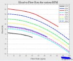
Now to the pump and figuring out my flow rates at different RPM's. I was unable to find Viron P280 pump curves online, but I did get in contact with them and *eventually* :grrrr: I was able to get some information. Their pump curve data shows 3 speeds (1375, 2000, and 3075 RPM) as well as power consumption and something else that I'm unfamiliar with. I would attach it, but the I have file size restrictions. I've basically mimicked their data in my Matlab chart anyway (see below). I wanted more speeds than they supplied, so I went into Matlab and did some math (fit a second order polynomial equation to their data, then plugged in a different Y intercept--this gives a decent approximation). I've plotted that data and attached it.
And last, but not least, I've hooked up a vacuum gauge and pressure gauge to my pumps suction and return sides, and I measured those as I went through several different RPM settings on the pump. Taking those two numbers, I multiplied the vacuum side (in HG) by 1.13 and the pressure side (psi) by 2.31 to get the TDH column. Then it's simply go to my Matlab chart, go up on the Y-axis to my RPM setting, along the curve until my head value and flow intersect. I've listed the flows in my excel data that I've attached as well.
So, now that I've probably got about 3 readers remaining , I come to the question portion.
(1) Am I right that the 62.8 gpm is my max flow rate for that size filter? It just says flow rate on the chart, not max. I haven't called the people at Cooper. I had been assuming it was max until I started writing this so I thought I'd ask.
(2) Is there anything you see wrong with my methodology? Am I correct in assuming that if my pump is on at 3075 RPM and thus flowing at 80 gpm, I may be overloading my filter and forcing sand into the pool?
(3) You may notice in my excel data that I'm getting 58 GPM at 2000 RPM, but dropping down a few RPM to 1925 and even to 1800 gives me 60 gpm. I guess that's due to better efficiency in that area possibly? The curves are leveling off down in that region. Also, as I'm typing this I just realized that those values are from my Matlab data, which likely has some amount error the farther we move to the right on the curves. Those RPM's and flow values are reasonably close, though.
(4) Also, at the low RPM settings my pressure side goes to 0, but I am getting flow from my returns in my pool. Do I need some minimum amount of pressure for my filter to run most efficiently?
Thanks for taking the time to read. I appreciate any responses or discussion.
I had a new pool installed last year, and I decided to go with a variable speed pump since it was for one reason or another free for me to upgrade to it. The pump itself is a Viron P280 variable speed pump with speed settings ranging from 1375 RPM to 3075 RPM. Last season, I noticed that occasionally the pump would blow sand (or what I think is sand) back into my pool. When I vacuum on filter, it spits it right back into the pool. I vacuumed on waste, and eventually, I had more in the bottom of the pool. I thought maybe I had cracked laterals, but that doesn't appear to be the case. Recently, I've been doing some research to figure out whether or not this pump, at 3075 RPM (which is it's automatic priming RPM when it turns on each time for 30 minutes), is giving too much flow for my filter. My filter is a 25" Cooper R series--I've attached the Data for it (the blue-ish background table. Any of the 25" models have the same specs, and if I'm reading it correctly, they have a max flow rate of 62.8 gpm. That's the first important number.
Now to the pump and figuring out my flow rates at different RPM's. I was unable to find Viron P280 pump curves online, but I did get in contact with them and *eventually* :grrrr: I was able to get some information. Their pump curve data shows 3 speeds (1375, 2000, and 3075 RPM) as well as power consumption and something else that I'm unfamiliar with. I would attach it, but the I have file size restrictions. I've basically mimicked their data in my Matlab chart anyway (see below). I wanted more speeds than they supplied, so I went into Matlab and did some math (fit a second order polynomial equation to their data, then plugged in a different Y intercept--this gives a decent approximation). I've plotted that data and attached it.
And last, but not least, I've hooked up a vacuum gauge and pressure gauge to my pumps suction and return sides, and I measured those as I went through several different RPM settings on the pump. Taking those two numbers, I multiplied the vacuum side (in HG) by 1.13 and the pressure side (psi) by 2.31 to get the TDH column. Then it's simply go to my Matlab chart, go up on the Y-axis to my RPM setting, along the curve until my head value and flow intersect. I've listed the flows in my excel data that I've attached as well.
So, now that I've probably got about 3 readers remaining
, I come to the question portion. (1) Am I right that the 62.8 gpm is my max flow rate for that size filter? It just says flow rate on the chart, not max. I haven't called the people at Cooper. I had been assuming it was max until I started writing this so I thought I'd ask.
(2) Is there anything you see wrong with my methodology? Am I correct in assuming that if my pump is on at 3075 RPM and thus flowing at 80 gpm, I may be overloading my filter and forcing sand into the pool?
(3) You may notice in my excel data that I'm getting 58 GPM at 2000 RPM, but dropping down a few RPM to 1925 and even to 1800 gives me 60 gpm. I guess that's due to better efficiency in that area possibly? The curves are leveling off down in that region. Also, as I'm typing this I just realized that those values are from my Matlab data, which likely has some amount error the farther we move to the right on the curves. Those RPM's and flow values are reasonably close, though.
(4) Also, at the low RPM settings my pressure side goes to 0, but I am getting flow from my returns in my pool. Do I need some minimum amount of pressure for my filter to run most efficiently?
Thanks for taking the time to read. I appreciate any responses or discussion.