Intermatic P1353ME Wiring/Hookup Question

Hi All,

First post here...I hope I can help you all out someday.

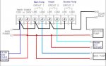
I need help/schematic in wiring a new Intermatic P1353ME and it will be replacing two Intermatic dial type timers.

I have the following equipment:

-Hayward Max Flo VS (This is a multi speed pump that turns on first and runs on high speed for a programmed time and then it will slow down to the next programmed speed and it will run at that speed until the power is disconnected and then the process will repeat the next time the power is restored. I just want it to run at high speed 3000 RPM for one hour and then drop to 2400 RPM for the rest of the day for a total of 8 hours of run time...I was planning on using circuit #1 to turn on at 0800 and stay on until 1600 so the pump will see power at 0800 and run at 3000 RPM and then after it has ran for 1 hour it will slow down to 2400 RPM for the rest of that day's cycle)

-Hayward 6060 Booster Pump (I want this to run for 1 hour and begin 15 minutes after the Max Flo VS has started running and then shut off. The manuals says that pool cleaners need to be connected to circuit #3 so I will setup this timer to start at 0815 and shut off at 0915)

-Compool LX-220 Solar Controller (This is 220 VAC and it needs to have power available at all times so that it can open and drain the solar panels when the temp gets below freezing. It has a relay that is used to turn off the Booster pump for 5 minutes after the valve to the solar panels is opened to avoid air being sucked into the Booster Pump during the time when the solar panels are filling with water)

-Hayward H300 gas heater (I believe this is supposed to be powered at all times however I heard that this is supposed to have a cool down...Naturally it has a thermostat and will fire up when the thermostat activates and it senses water flow. We never used it because the solar is good enough however I want to install it correctly so the cool down is safe for the system)

-We have pool lights however I do not want automation for these

Naturally the pool has a 220VAC power panel with two side by side circuit breakers (220VAC) and a single 110 VAC circuit breaker. The pool lights are tapped off right away and have a small switch located inside of a 110VAC outdoor style metal power receptacle box where on spring loaded cover houses the light switch and the other cover houses the 110 VAC outlet)

The big question is how do I wire up all of this stuff up???

Any help would be GREATLY appreciated and I have posted numerous help on other forums to help people out and I will continue to pay it forward in the future!!!

THANKS!!!

Bill :paddle:
 
The big question is how do I wire up all of this stuff up???
Do you need instruction on what connections to make or do you need instruction on how to run conduit, pull wire , make termination connections, etc? What skill level do you have when working with electric? Do you have a fundamental understanding of NEC article 680?
This is not meant to sound harsh/rude, but it is a pretty simple question for a fairly complicated job. Fill in the blanks a bit and I am sure we can help you with what you need to do. Also, we like pictures. In this case, they will be a big help.
 
This is not meant to sound harsh/rude, but it is a pretty simple question for a fairly complicated job. Fill in the blanks a bit and I am sure we can help you with what you need to do. Also, we like pictures. In this case, they will be a big help.

No...not rash or rude...GOOD and PERTINENT QUESTIONS...sorry I was not more clear as my post was already very long.

I already have the conduit and wires run as they were already installed and it was running until the clock stopped working. I am familiar with the NEC and safe work with electrical wire however the wiring up of the equipment in a manner that will ensure all of the automation is working correctly is still a question.

Things like should the heater be connected to continuous electrical power or should it be connected to the same timer function as the main pump? I would think the pump should be on #1 and run from 0800 to 1600 and the heater should be connected to #2 and be electrically powered from 0830 to 1530 so as to allow the pump to purge and flow water through the heater elements before the heater starts and for 30 minutes after the heater shuts off. I assume the H300 heater is OK with being up and running and heating the water and then having its power being shut off while it is still heating?

The LX-220 (I verified it is wired for 220VAC) it seems should be energized 24/7 because it should be able to open and close the valve to the solar collectors when the temperature begins to freeze.

The Intermatic manual states that "cleaning equipment" must be placed on #3 so I assume they are meaning the booster pump so I must wire it to #3.

Is there anything I am not considering???

IF all of the above are true statements, then all I need to know now is how to wire up the components.


THANKS AGAIN FOR ALL OF YOUR HELP!!!

Bill
 
Here's a wiring diagram that should get you what you need.

Set the timer to mode #3 and program a cool down time as shown on page 28 of the manual.
Also hook the hot leg of the booster pump through the solar relay so that it can stop the booster pump when priming the panels.

The good thing about this is that it leaves you an open circuit that you can use for something else.

P1353ME Wiring Firemans Sw.jpg
 
Dave,

I am VERY GRATEFUL for your time and help on this!!!

I took your schematic and added some components and some colors so as to be able to follow the wires more clearly (plus it looks cool).

Is this about right?

I understand the need to connect the booster pump to a relay controlled by the LX-220 Solar Controller so in that manner the booster pump will shut down for about 5 minutes during the time the solar panel diversion valve opens to direct the water to the solar panels and therefore it will clear the air out of the pipes.

I do understand the need for heater cool down (10 minutes before the pool pump stops) however I do not understand the wiring of the heater nor do I understand the Fireman Switch concept (my guess is that the Fireman Switch is a normally open switch that is located near the equipment so that in the case of a heater fire the fireman will push the Fireman Switch and close the circuit and this will tell the Intermatic to shut off power to the heater???)


How does the heater get it's 220 VAC power? Would I need to wire up the heater to Circuit #2 so that it has timer switched power?

Regarding the Firemans Switch, I do not have a Fireman's Switch however since the manual states "The cool down time is a time defined by the programmer (me...when I get a chance to learn how to program this magic box). It is used inconjunction with a pool heater and it's defined as the additional time the pump will run over and beyond the desired pump off time with the fireman switch open"

So do I correctly understand that since I do not have the Fireman Switch that I should clip the wire for the Fireman Switch (opening the circuit) and this will tell the Intermatic that there is no fire (Fireman Switch is open) and it will then run the pump an extra amount of time (that I programmed in mode #3) so as to allow for the safe cool down of the heater?

If this is so then where does the heater get it's power from? If I wire it directly to the 220 VAC circuit breaker then it will be powered continuously and it will not shut off until it senses no water flow.

:confused::confused::confused::confused::confused::confused::confused::confused::confused::confused::confused::confused::confused:

THANKS AGAIN for all of your time and help...GREATLY APPRECIATED!!!
Bill
 

Attachments

  • Pool Pump Wiring.jpg
    Pool Pump Wiring.jpg
    58 KB · Views: 100
The 'Firemans switch' nomenclature is a little misleading. It's actually a normally closed switch that when open prevents the heater from firing. In this case it's simply a remote switch that disables the heater operation without removing power to the heater.

[NOTE: If you don't use the firemans switch, leave the existing loop of wire in place.]

Your heater has a remote on/off switch connection and that's where the firemans switch would be connected. It's on page 18 of the heater manual, middle graphic.

Having said that, you can certainly wire it like you have it shown above, but it makes the programming a little more cumbersome. If you use the firemans switch and program the cool down time, then it's set no matter when you program the main pump to run.

If you wire it like you have it shown, you have to program the heater shutoff independently of the main pump, so whenever you change the main pump run time you have to reprogram the heater times. With the firemans switch setup if you change the pump run time, the cool down timer still follows the pump run time without having to reprogram the heater cool down.
 
> you can certainly wire it like you have it shown above, but it makes the programming a little more cumbersome. If you use the firemans switch and program the cool down time, then it's set no matter when you program the main pump to run.

If you wire it like you have it shown, you have to program the heater shutoff independently of the main pump, so whenever you change the main pump run time you have to reprogram the heater times. With the firemans switch setup if you change the pump run time, the cool down timer still follows the pump run time without having to reprogram the heater cool down.

THANK YOU ALL for the assistance and advice!!!

The Fireman Switch concept is cleaver however it might just be a bit too cleaver for this pool and it's owner. In four years we have not run the pool heater because the owner is too cheap (that is why I am on this forum instead of throwing money at someone to do it) and the solar works pretty good.

Today (I hope) is the day I dive into this wiring project and I will report back on my progress or lack there of. Looks like if I wire the heater to Circuit #2 I will need to use Mode 1 for the programming features because the manual says that in Mode 1 all loads are independently controlled.

Wish me luck as I dive in (no pun intended with respect to pools and 220 VAC electricity).

THANKS AGAIN!!!

Bill
 

Enjoying this content?

Support TFP with a donation.

Give Support
Hi All!!!

Success!!! I FINALLY got this thing all connected and up and running. Only a little bit of the smoke came out of the Intermatic P1353ME when I connected it up however there must still be some smoke left in there because it is running as advertised. The pool water was a bit "tingly" at first until I realized that that raw wire was dangling in the pool...the kids are much better now and should be released from hospital today.

Anyhoo...all is well and I REALLY THANK YOU for your advice and help on getting this thing wired up!!!

Bill
 
Thread Status
Hello , This thread has been inactive for over 60 days. New postings here are unlikely to be seen or responded to by other members. For better visibility, consider Starting A New Thread.