T10604 wiring problem

Mar 4, 2015
45
Iowa
I believe I havevthis wired correctly, the 104 side w orks fine with 120 v from 4 on the 104 and 120 v on two from the 106. When I turn the 106 on I get 120v from 4(common) on the 104 and 2 ( red low speed) and black line 2 high speed on 3 of the 106 resulting in the motor reset kicking out. The motor works fine when wired directly to either white and black or white and red. I'm banging my head against the wall!

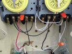
The black,red, and white on the left are from the motor, L1 black, L 2 white and A red. The white on the left bottom is 110 common (line) and the black 110 line.

The wire nut extends the common wire from the motor and is not connected to the white from the 110 feed though it may appear that way from the picture angle.
 

Attachments

  • image.jpg
    image.jpg
    69.5 KB · Views: 69
Don't these come with a wiring diagram? If not, should be easy to find one online.

Is the power source 120V or 240V? Is the motor 120V or 240V?
The power source is 240 v and the motor is 240v. I just used a piece of 12/2 with ground for my short run from the 20 amp gfi double pole breaker to the timer. I have followed the wiring diagram, one thing that irritates me about this timer is the first step in wiring it is you take the white motor wires from the 106 and put them on 1 and 3 of the 104. Isn't this something that should already be done at the factory?
 
You said "one thing that irritates me about this timer is the first step in wiring it is you take the white motor wires from the 106 and put them on 1 and 3 of the 104. Isn't this something that should already be done at the factory?"
The timers are bought separately. So if you want them to work together you have to feed them from the same source.

- - - Updated - - -

In your first post you mention 110V There should really be NO 110V in this circuit. (yes I know that 110V is just 1/2 of the 220V service, but we aren't using it that way)
Did you mean to say 220V??
 
You said "one thing that irritates me about this timer is the first step in wiring it is you take the white motor wires from the 106 and put them on 1 and 3 of the 104. Isn't this something that should already be done at the factory?"
The timers are bought separately. So if you want them to work together you have to feed them from the same source.

In the case of this timer, (10604) they both came installed in the same waterproof enclosure from the factory, it would be nice if the first step ( re-wiring timers) was accomplished there.

- - - Updated - - -

In your first post you mention 110V There should really be NO 110V in this circuit. (yes I know that 110V is just 1/2 of the 220V service, but we aren't using it that way)
Did you mean to say 220V??

Yes I meant 220 but as you know, no single wire is going to give you 220 volts so I am talking 1/2 of the 220 service.


W
 
Okay, then the only thing I can see that keeps popping out at me is that RED and BLACK from the motor might be reversed. Otherwise, your hookup looks correct. The 106 is the timer on the left, correct?

- - - Updated - - -

Yes I meant 220 but as you know, no single wire is going to give you 220 volts so I am talking 1/2 of the 220 service.


W

True, but at no point in this exercise are we looking at them separately, it's always 220V at every step of the way.
 

Enjoying this content?

Support TFP with a donation.

Give Support
Sure hope I haven't 'put you off' on this. I really enjoy electrical stuff and mysteries. If you put the two together, I'm all in!!
Sorry about the late reply, couldn't sleep last night because of storms and then I slept like a baby 1/2 hour before I had to get up. I just tested the voltage at several stages, keep in mind the 106 is on the left and the 104 on the right.
104 with lever turned off 1&3 240v 1&4 110v. Turned on 1&3 240v 1&4 240 v. With the 106 off and the 104 on 2 on 106 and 4 on 104 is 240, 3 on 106 is 0, turn on 106 and 2&3 are 240 2 from 106 and 4 from 104 is 240, 3 from 106 and 4 from 104 is 240. Pump overload kicks off and resets in a few minutes.
 
I am using that very good info to look at this. I'm worried that there is a voltage at 1 and 4 on the 104 timer when in the off position...

- - - Updated - - -

It's almost like L2, at the motor, is grounded somehow...
 
That's what I see. One of the wires from the motor (possibly L2) is grounded some how.

If you look at this diagram: http://waterheatertimer.org/images/T106-T104-400.jpg

With 104 off there is no path from GND to 4 on 104. So there should be no voltage there.
1-2 should be 0
1-3 should be 220
1-4 should be 0
in fact any other combination on 104 should be 0

- - - Updated - - -

So what's happening is with 106 and 104 both on, the motor is getting both the high speed winding and the low speed winding. This is a No No and is overheating it.

- - - Updated - - -

An easy check would be this: With both timers switched in the off position there should only be voltage at 1-3 of the 104 timer. No voltage at all anywhere else.

Ok before I was checking voltage with the 104 off between 1 and 4 and got voltage but when I go from ground to 4 no voltage only voltage from ground to 1 and 3
 
Danpic, I don't know what happened to my connection pictures or you reply but I replied earlier and know don't see it. Anyway I took off the white from the motor on 4 and there is no voltage from 1 to 4. I am going to temporarily wire it with new wire to rule out the knick even though I hope that's i, otherwise what are my options ? Replacement motor? Why woesnt the gfi kick out?
 

Enjoying this content?

Support TFP with a donation.

Give Support
Thread Status
Hello , This thread has been inactive for over 60 days. New postings here are unlikely to be seen or responded to by other members. For better visibility, consider Starting A New Thread.