I have a Hayward Tri-Star 2 speed pump and just purchased an Intermatic T104R. After doing more research I see I should have ordered the T10604R. I assume this because you have to have a controller for each speed. From what I am reading it is most efficient to run the pump on low all of the time with the exception of cleaning tools attached to the skimmer. Could I just get by with the 104 then and manually switch to high speed when cleaning the pool?

2 speed pumps and timers
- Thread starter Scottman
- Start date
You are using an out of date browser. It may not display this or other websites correctly.
You should upgrade or use an alternative browser.
You should upgrade or use an alternative browser.
My 2 speed pump just has the rocker switch on it-----middle position being OFF. Works for me just to hit the button!
I was doing some more research and found that the red wire feeds the low speed on the motor and the black the high. My question is does this mean it is running at 110 when on low speed and high required both legs of the 110? If this is the case I could use the 104 for all pumping needs then just manually switch on the black for cleaning the pool. Is this right?
I have no idea, but why not just hit the button on the pump?
There is no button on the pump that I can see only white,red,and black wires. The pump is fresh out of the box and hasn't been installed yet. I know it's latenin the season to be starting a pool but due to some shipping problems with mt wall panels from a company that shall remain nameless unless they validate their warranty, I am a less than a week away from adding water

")
- Jun 22, 2014
- 47,754
- Pool Size
- 17888
- Surface
- Fiberglass
- Chlorine
- Salt Water Generator
- SWG Type
- CircuPool RJ-45 Plus
A 2-speed pump with no toggle switch? I may have to Google that model to see how they expect an owner to change between speeds. My 2-speed has a toggle switch. It's 110V regardless of what speed it's on.
- May 3, 2007
- 16,833
- Pool Size
- 20000
- Surface
- Plaster
- Chlorine
- Salt Water Generator
- SWG Type
- Hayward Aqua Rite (T-15)
NO!I was doing some more research and found that the red wire feeds the low speed on the motor and the black the high. My question is does this mean it is running at 110 when on low speed and high required both legs of the 110? If this is the case I could use the 104 for all pumping needs then just manually switch on the black for cleaning the pool. Is this right?
There are two sets of windings on a two speed motor and they both use the same voltage but you must not energize both windings at the same time. You energize one of the windings for high speed and the other for low speed. This is why a SPDT switch is required to switch between the two windings. However, there is a common wire for both sets of windings which is why there are three wires feeding a two speed motor (plus ground).
What is a Single Pole Double Throw (SPDT) Switch may be helpful.
In this case, the white is common between the two windings and your switch selects between the red and black wire thus switching between high and low speeds.
In this case, the white is common between the two windings and your switch selects between the red and black wire thus switching between high and low speeds.
- May 7, 2013
- 50
- Pool Size
- 20000
- Surface
- Plaster
- Chlorine
- Salt Water Generator
- SWG Type
- CircuPool Core-55
A 2-speed pump with no toggle switch? I may have to Google that model to see how they expect an owner to change between speeds. My 2-speed has a toggle switch. It's 110V regardless of what speed it's on.
Many two speed motors use a mechanical 24 hour timer to switch between low and high speed automatically.
The TriStar 2 speed pump has never come with a installed switch for switching between speeds. You need an external switch to do this. Mas985 hit it on the nose. Be careful.
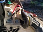
Here is a picture of the pump wiring. And yes I get 110v between 1 and 4 on the 104 when both switches are in they off postition. Is there a chance I got the timer motor wires switched from the 106 when I moved them over that could cause this? I checked the back of both timers and the top wire goes to 1 and the bottom to 3. Thanks again for your time and help!
Attachments
Nope. You've got a short in one of the windings from the motor to ground. Easy to check. Unhook all wires from motor. Check for voltage at 1 and 4 on t104. It will not be there.
- - - Updated - - -
Or one of the wires from the motor to the timer box has a nick and is shorting to the ground wire.
- - - Updated - - -
Because 4 only goes to L2 on the motor and nowhere else with T104 off.
What do you measure between 3 and 4 on T104 in the off position?
- - - Updated - - -
Or one of the wires from the motor to the timer box has a nick and is shorting to the ground wire.
- - - Updated - - -
Because 4 only goes to L2 on the motor and nowhere else with T104 off.
What do you measure between 3 and 4 on T104 in the off position?
Oh, in answer to to your question about the clock modules, no. They are AC modules, with shaded pole motor. It doesn't matter which way you wire them in as long as they are wired to the feed from the breaker, which they are.
Nope. You've got a short in one of the windings from the motor to ground. Easy to check. Unhook all wires from motor. Check for voltage at 1 and 4 on t104. It will not be there.
- - - Updated - - -
Or one of the wires from the motor to the timer box has a nick and is shorting to the ground wire.
- - - Updated - - -
Because 4 only goes to L2 on the motor and nowhere else with T104 off.
What do you measure between 3 and 4 on T104 in the off position?
I get 120v between 3&4 in off position and yes, when I disconnect the white on 4 there is no voltage between 1 and 4.
I don't know how to check for a ground on windings, probably my next step is to temporarily wire a new piece of 14/3 to eliminate or confirm a nicked wire, which I hope is the case?
If you have an ohm meter (resistance) selection on your tester you could do that between the motor connections and the body of the motor. Should be 0. Any reading means a short.
I get 120v between 3&4 in off position and yes, when I disconnect the white on 4 there is no voltage between 1 and 4.
I don't know how to check for a ground on windings, probably my next step is to temporarily wire a new piece of 14/3 to eliminate or confirm a nicked wire, which I hope is the case��
If you are going to pull new wire, do not use Romex. You have a couple of code violations going on here. Romex is not rated for wet applications. Any conduit used outdoors including Greenfield, liquidtight, etc is classified as a wet application even though it might stay dry inside. All wiring used in this application needs to be rated THWN. also, the ground wire in this application HAS to be insulated (green).
You should also wrap the wires around the screws in the same direction as the screw tightens
If you have an ohm meter (resistance) selection on your tester you could do that between the motor connections and the body of the motor. Should be 0. Any reading means a short.
Ohms between motor casing or ground an all three leads is 0, between leads os 22-30. Also when I disconnect black (line1) and red (a) I still get 110v from 1 and 4 on 104 but when I disconnect white( common) in 4,I get 18 volts between 1 and 4. Could it be a bad timer?
0 ohm reading is bad. It means what I was afraid of. Somehow your motor windings are shorted to your motor casing. There really isn't an easy way to fix this. I could tell you a way to make it work but it would not be safe.
Disconnect all motor leads from the timers. WIth both off check the voltages. Should only be a voltage on 1 and 3, on the 104 and nowhere else. If you are using a digital meter, I bet if you look close that 18 volts isn't volts but mV. It comes from stray current in the area of the timer clocks. If it really is volts, then your 104 timer might have a sticky relay contact. But I doubt it. It's very rare that a sticky contact shows a low voltage, usually they stick either ON or OFF. But it is possible.
Disconnect all motor leads from the timers. WIth both off check the voltages. Should only be a voltage on 1 and 3, on the 104 and nowhere else. If you are using a digital meter, I bet if you look close that 18 volts isn't volts but mV. It comes from stray current in the area of the timer clocks. If it really is volts, then your 104 timer might have a sticky relay contact. But I doubt it. It's very rare that a sticky contact shows a low voltage, usually they stick either ON or OFF. But it is possible.
0 ohm reading is bad. It means what I was afraid of. Somehow your motor windings are shorted to your motor casing. There really isn't an easy way to fix this. I could tell you a way to make it work but it would not be safe.
Disconnect all motor leads from the timers. WIth both off check the voltages. Should only be a voltage on 1 and 3, on the 104 and nowhere else. If you are using a digital meter, I bet if you look close that 18 volts isn't volts but mV. It comes from stray current in the area of the timer clocks. If it really is volts, then your 104 timer might have a sticky relay contact. But I doubt it. It's very rare that a sticky contact shows a low voltage, usually they stick either ON or OFF. But it is possible.
I'm confused, in an earlier post any reading ohm other than zero was a problem and now you say zero is a problem. I did another check and it is definitely 18 V between one and four. Thank you for your patience with helping me with this I'm just getting frustrated because the motor and pump were brand new out of the box a week ago and seems to work fine when wired directly. I was looking forward to cranking up the heater and using it this weekend and now I feel it isn't safe. I can't understand how the gfi isn't tripping if I have a short in the motor.
Well heck!! I thought I was keeping good track of this one...
Let's kinda reboot here.
Looking at your first post with the picture of the timers and how you have them wired. That looks correct!
The timer on the left is the 106. it's clock is connected to the same place that the 104 clock is connected. Correct!
The timer on the right is the 104. it has the incoming power from the double breaker connected to 1-3. Correct!
There is a jumper between 1-4 on the 106. Correct!
There is a jumper between 1-3 on the 104 Correct!
With no motor wires connected to any of the timers.
And both timers OFF. You should read the following.
0V on all connections except for 220V between 1-3 on 104
Turn on the left timer (104). Still no motor leads on
220V between 1-3 on 104
220V between 1-4 on 104
220V between 2-3 on 104
220V between 2-4 on 104
0V between 1-2 on 104
0V between 3-4 on 104
Keep 106 OFF
0V on all connection on 106
220V between 1 on 106 and 3 on 104
220V between 1 on 106 and 4 on 104
220V between 4 on 106 and 3 on 104
220V between 4 on 106 and 4 on 104
220V between 2 on 106 and 3 on 104
220V between 2 on 106 and 4 on 104
0V between 3 on 106 and ALL on 104
Turn on 106
0V on all connection on 106
220V between 1 on 106 and 3 on 104
220V between 1 on 106 and 4 on 104
220V between 4 on 106 and 3 on 104
220V between 4 on 106 and 4 on 104
220V between 3 on 106 and 3 on 104
220V between 3 on 106 and 4 on 104
0V between 2 on 106 and ALL on 104
Thread Status
Hello , This thread has been inactive for over 60 days. New postings here are unlikely to be seen or responded to by other members. For better visibility, consider Starting A New Thread.