
Hello, I have a problem! I'm looking for the wise and knowledgable person to help with a wiring issue.
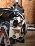
Problem is that I have said pump, but the 115/230V jumper broke into half a dozen pieces while working on it.
I don't know what the jumper was jumping. I'm on hold to Hayward now to get a replacement part but in the meantime I need to get the water moving.
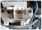
I figure I can solder together a jumper but need to know what gets jumped as I didn't get a good look at the jumper set up before it crumbled.
Can anyone give me an idea? I need a 230V jumper setup. Attached are a couple pictures I scavenged from the internet.
My unit is Model C48L2N134B3. Serial 8E06. 1.5HP, SF1.0, 56J, 115/230V.
________________________________________________________________________________________________________________________________
Answer received from Hayward, the guy was super helpful by the way...cap off the white (black stripe) wire and connect the solid black to the far right terminal.
The guy is sending me a plug free of charge from decommissioned units they have sitting in the lab.
________________________________________________________________________________________________________________________________
Problem is that I have said pump, but the 115/230V jumper broke into half a dozen pieces while working on it.
I don't know what the jumper was jumping. I'm on hold to Hayward now to get a replacement part but in the meantime I need to get the water moving.
I figure I can solder together a jumper but need to know what gets jumped as I didn't get a good look at the jumper set up before it crumbled.
Can anyone give me an idea? I need a 230V jumper setup. Attached are a couple pictures I scavenged from the internet.
My unit is Model C48L2N134B3. Serial 8E06. 1.5HP, SF1.0, 56J, 115/230V.
________________________________________________________________________________________________________________________________
Answer received from Hayward, the guy was super helpful by the way...cap off the white (black stripe) wire and connect the solid black to the far right terminal.
The guy is sending me a plug free of charge from decommissioned units they have sitting in the lab.
________________________________________________________________________________________________________________________________
Attachments
Last edited: