New Liquidator installation

rohan

0
LifeTime Supporter
Mar 23, 2009
36
Hi there - have just shifted back to BBB after 3 years of using a Hayward puck Chlorinator and not noticing my CYA rise until I had a big algae problem that required me to drain and restart with BBB to get under control.
Like the results using Walmart bleach and now looking for a way to not have to walk out to the pool every evening to top the chlorine off.
Researched this forum and decided to buy the Liquidator and have just received it.
My son (engineering sophomore in college!!) has read through the installation instructions and tells me that this is as simple as disconnecting the Hayward from the tubes and attaching them to the Liquidator. That the holes are already in exactly the right place for the installation. Could this be true?
I did not read anywhere on the forum that it would be that simple to convert from an already-installed puck-based chlorinator to the liquidator, so thought I would shoot out a quick note before we attempted this for real tomorrow.
Any guidance would be deeply appreciated. Thanks.
 
The output of the Liquidator needs to be connected to the suction side of the pump. Both of my puck chlorinator's lines were connected to the pressure side so only the input side of the Liquidator could use one of the existing chlorinators tubes. I suggest that you connect the Liquidator output to your pump basket drain port. Tap a hole on the pressure side for the Liquidators input . This will allow you to keep the puck chlorinator installed in the case where you may need to use pucks
 
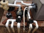
Chl-Installation.JPG

Pic attached...looks like I have a tap both into the suction side and the output side...seems like based on the advice provided I could just resuse the taps unless I want to preserve the puck chlorinator in which case I can use the bottom of the pump filter basket as the suction area and drill another hole on the pressure side?

Any pros/cons to using the pump filter basket vs the old puck lines? Is there a pic available on the forum that shows how to bring the filter basket into the installation? Do I have to drill another hole there?

Thanks for the help...
 
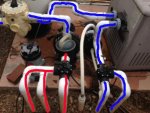
Wow!!! Guess I've been looking at this all wrong. Can you please help me identify the suction side from the pressure side? I have always thought that the flow was from the 3-legs into the filter basket, into the filter, then back out through the pipe just below the pipe with the tap, into the water heater, then back out through the 2-leg slide into the pool that also has a tap for the puck-based chlorinator. Do I have the flow correct? If so, which is the suction side and which is the pressure side? And how does the filter basket factor into this equation? Would I need a special connector to connect directly to the drain plug of the basket? Thanks.
 
Huh? That sounds different than what laprjns is saying. By your method, the tap to the right of the multivalve (SW quadrant) would be the suction side. And the other tap in the SE quadrant would be the pressure side. Which would mean that I do have the correct taps for a Liquidator already without needing more holes or tapping into the filter basket. I'm confused....
 
attachment.php


Red is suction side, blue is pressure side. Pump filter basket is on the suction side just before the pump intake. The white pipe coming out of the top of the pump and then over to the multivalve is on the pump discharge side which is pressurized.
 

Attachments

  • Chl-Installation.jpg
    Chl-Installation.jpg
    24.2 KB · Views: 204

Enjoying this content?

Support TFP with a donation.

Give Support
Laprjns and I are in complete agreement. His pictures demonstrate it well.


Edit: SW means lower left quadrant. The tap to the right of the multivalve is in the upper left NW quadrant.
 
Last edited:
Gtemkin - Laprjns - you guys are amazing!!! Completely agree with Kim. Thanks for taking the time out of your Sunday to educate me on all of this. The pics make it clear!!!

Just a few more questions and I think I'll have enough to proceed with confidence.

(1) I like the idea of keeping the puckintor around in case of emergencies. Now I understand that the puckinator has both taps in the pressure (blue) side of the drawing, which would only be good for the input side of the liquidator. Do you have a recommendation based on my drawing of where to drill another hole on the pressure side for the input to the liquidator?

(2) For the output side, how exactly do I tap into the pump filter? I see the drain plug and I have never used this before, but assume you just screw it off to remove. Then, is there a special connector needed to make the connection to the output tube for the liquidator? How exactly do you attach to it?

Thanks again guys!!! We now have great marked before pics...I'll take some after and post in case this thread could be helpful to other newbys like me on the forum.
 
(1)Do you have a recommendation based on my drawing of where to drill another hole on the pressure side for the input to the liquidator?
Should be after the filter, so i would tap a hole on the back pipe that goes from the multivalve to the heater.

(2) For the output side, how exactly do I tap into the pump filter? I see the drain plug and I have never used this before, but assume you just screw it off to remove. Then, is there a special connector needed to make the connection to the output tube for the liquidator? How exactly do you attach to it?
You need to get an nylon fitting to screw into where the plug was. It is most likely a 1/4 NPT but you need to check this. Should look something like this. Oryou could tap a hole in one of the pipes on the suction side and used the saddle clamp fitting that was supplied with the Liquidator.
 
Thread Status
Hello , This thread has been inactive for over 60 days. New postings here are unlikely to be seen or responded to by other members. For better visibility, consider Starting A New Thread.