Hello all,
I think I have a problem with my timer. It has been working fine for years, but the other day it started acting up. It is set to turn on at noon and off at 8pm. It will turn on at noon like it is supposed to, but then won't turn off at 8pm or at all. Meaning the [Filter] button will not turn the motor on and off like it should. I cannot put it in service mode and stop the pump either. To turn off the pump, I have to shut everything down with the breakers. Then turn on the Aqualogic unit. Then turn everything else on ten seconds later and then I can turn the pump on and off at will. The next day at noon, the pump will turn on as it should, but then at 8pm it continues to run and I cannot turn it off unless I reset the system again.
All of the relays work fine. I swapped relays anyway and it does the same thing. I also know that the relays work fine, because after I reset the system, they all work properly.
Any suggestions as to where to go from here is appreciated. Thank you!
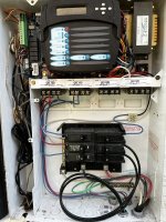
It’s a Hayward Goldline AquaLogic AQL-PS-4
I think I have a problem with my timer. It has been working fine for years, but the other day it started acting up. It is set to turn on at noon and off at 8pm. It will turn on at noon like it is supposed to, but then won't turn off at 8pm or at all. Meaning the [Filter] button will not turn the motor on and off like it should. I cannot put it in service mode and stop the pump either. To turn off the pump, I have to shut everything down with the breakers. Then turn on the Aqualogic unit. Then turn everything else on ten seconds later and then I can turn the pump on and off at will. The next day at noon, the pump will turn on as it should, but then at 8pm it continues to run and I cannot turn it off unless I reset the system again.
All of the relays work fine. I swapped relays anyway and it does the same thing. I also know that the relays work fine, because after I reset the system, they all work properly.
Any suggestions as to where to go from here is appreciated. Thank you!
It’s a Hayward Goldline AquaLogic AQL-PS-4
Attachments
Last edited: